CLK
WDOG
en
Mod = = Timer?
Test
32-bit Timer
Modulus Register
(Time-out Value)
WDOG
Reset
Nth Stage Overflow Enables N + 1th Stage
en en
Reset Value (Hardwired)
Byte
Stage 4
Equality Comparison
Byte 4
Byte 2
Byte 1
Byte 3
Byte
Stage 3
Byte
Stage 2
Byte
Stage 1
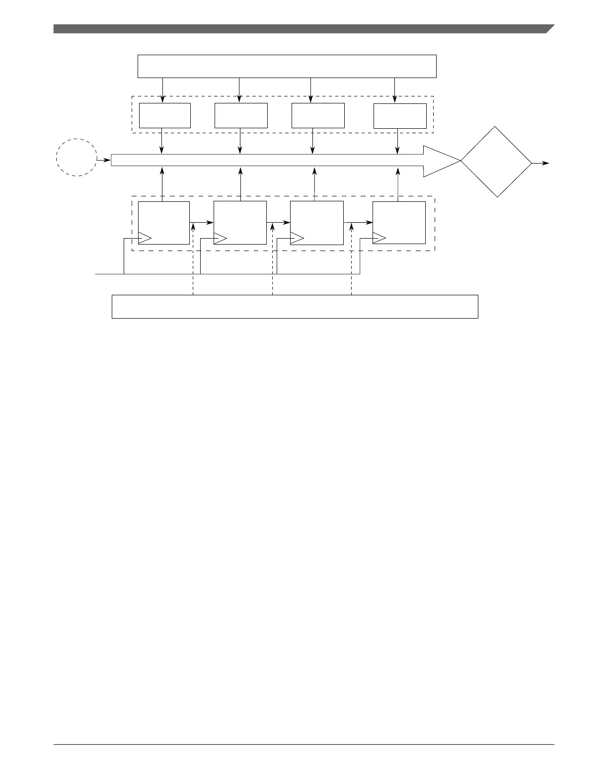
Figure 24-2. Watchdog timer byte splitting
Each stage is an 8-bit synchronous counter followed by combinational logic that
generates an overflow signal. The overflow signal acts as an enable to the N + 1th stage.
In the test mode, when an individual byte, N, is tested, byte N – 1 is loaded forcefully
with 0xFF, and both these bytes are allowed to run off the clock source. By doing so, the
overflow signal from stage N – 1 is generated immediately, enabling counter stage N.
The Nth stage runs and compares with the Nth byte of the time-out value register. In this
way, the byte N is also tested along with the link between it and the preceding stage. No
other stages, N – 2, N – 3... and N + 1, N + 2... are enabled for the test on byte N. These
disabled stages, except the most significant stage of the counter, are loaded with a value
of 0xFF.
24.5
Backup reset generator
The backup reset generator generates the final reset which goes out to the system. It has a
backup mechanism which ensures that in case the bus clock stops and prevents the main
state machine from generating a reset exception/interrupt, the watchdog timer's time-out
is separately routed out as a reset to the system. Two successive timer time-outs without
an intervening system reset result in the backup reset generator routing out the time-out
signal as a reset to the system.
Chapter 24 Watchdog Timer (WDOG)
K22F Sub-Family Reference Manual, Rev. 4, 08/2016
NXP Semiconductors 527

 Loading...