FTMx_FLTPOL field descriptions (continued)
Field Description
0 The fault input polarity is active high. A 1 at the fault input indicates a fault.
1 The fault input polarity is active low. A 0 at the fault input indicates a fault.
1
FLT1POL
Fault Input 1 Polarity
Defines the polarity of the fault input.
This field is write protected. It can be written only when MODE[WPDIS] = 1.
0 The fault input polarity is active high. A 1 at the fault input indicates a fault.
1 The fault input polarity is active low. A 0 at the fault input indicates a fault.
0
FLT0POL
Fault Input 0 Polarity
Defines the polarity of the fault input.
This field is write protected. It can be written only when MODE[WPDIS] = 1.
0 The fault input polarity is active high. A 1 at the fault input indicates a fault.
1 The fault input polarity is active low. A 0 at the fault input indicates a fault.
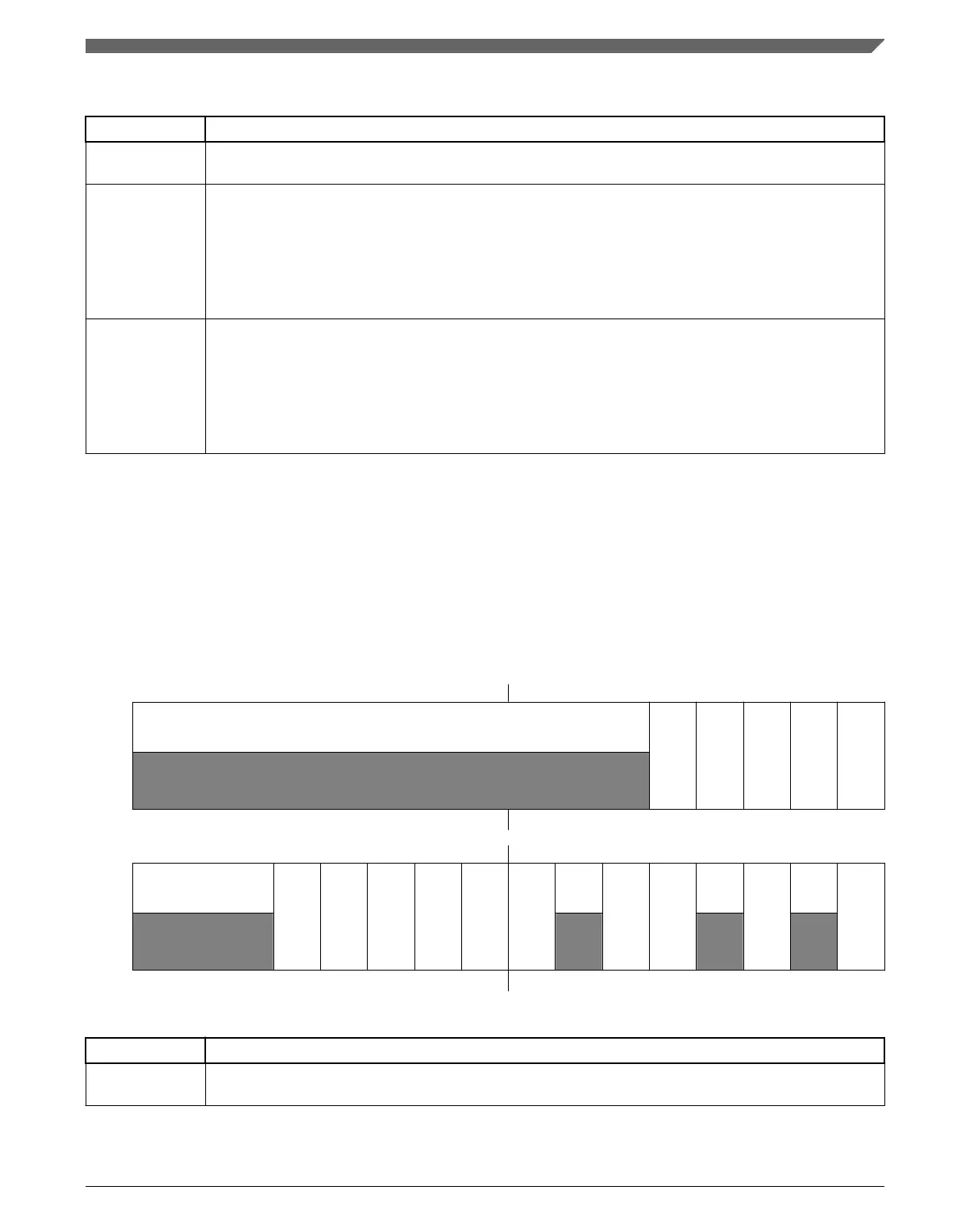
39.3.24 Synchronization Configuration (FTMx_SYNCONF)
This register selects the PWM synchronization configuration, SWOCTRL, INVCTRL
and CNTIN registers synchronization, if FTM clears the TRIGj bit, where j = 0, 1, 2,
when the hardware trigger j is detected.
Address:
Base address + 8Ch offset
Bit 31 30 29 28 27 26 25 24 23 22 21 20 19 18 17 16
R
0
HWSOC
HWINVC
HWOM
HWWRBUF
HWRSTCNT
W
Reset
0 0 0 0 0 0 0 0 0 0 0 0 0 0 0 0
Bit
15 14 13 12 11 10 9 8 7 6 5 4 3 2 1 0
R
0
SWSOC
SWINVC
SWOM
SWWRBUF
SWRSTCNT
SYNCMODE
0
SWOC
INVC
0
CNTINC
0
HWTRIGMOD
E
W
Reset
0 0 0 0 0 0 0 0 0 0 0 0 0 0 0 0
FTMx_SYNCONF field descriptions
Field Description
31–21
Reserved
This field is reserved.
This read-only field is reserved and always has the value 0.
Table continues on the next page...
Chapter 39 FlexTimer Module (FTM)
K22F Sub-Family Reference Manual, Rev. 4, 08/2016
NXP Semiconductors 939

 Loading...