39.4.12 Inverting
The invert functionality swaps the signals between channel (n) and channel (n+1)
outputs. The inverting operation is selected when:
• QUADEN = 0
• DECAPEN = 0
• COMP = 1, and
• INVm = 1 (where m represents a channel pair)
The INVm bit in INVCTRL register is updated with its buffer value according to
INVCTRL register synchronization
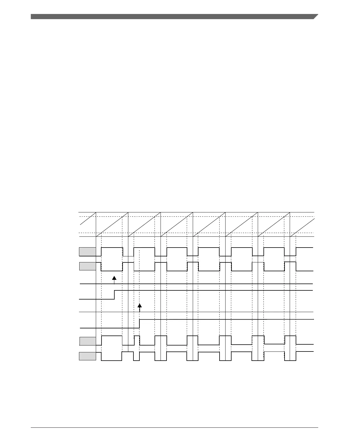
In High-True (ELSnB:ELSnA = 1:0) Combine mode, the channel (n) output is forced low
at the beginning of the period (FTM counter = CNTIN), forced high at the channel (n)
match and forced low at the channel (n+1) match. If the inverting is selected, the channel
(n) output behavior is changed to force high at the beginning of the PWM period, force
low at the channel (n) match and force high at the channel (n+1) match. See the following
figure.
NOTE
channel (n+1) match
FTM counter
channel (n) match
channel (n+1) output
before the inverting
write 1 to INV(m) bit
INV(m) bit buffer
INVCTRL register
synchronization
INV(m) bit
channel (n) output
after the inverting
channel (n+1) output
after the inverting
INV(m) bit selects the inverting to the pair channels (n) and (n+1).
channel (n) output
before the inverting
Figure 39-63. Channels (n) and (n+1) outputs after the inverting in High-True
(ELSnB:ELSnA = 1:0) Combine mode
Chapter 39 FlexTimer Module (FTM)
K22F Sub-Family Reference Manual, Rev. 4, 08/2016
NXP Semiconductors 989
 Loading...

