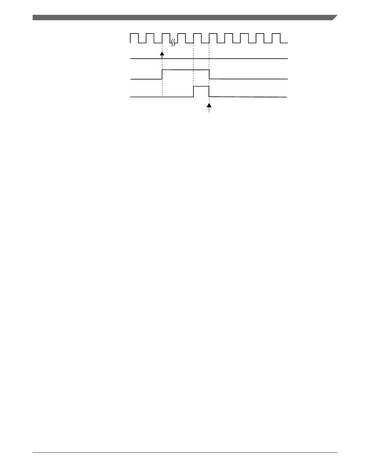
system clock
OUTMASK register is updated and
TRIG0 bit is cleared
write 1 to TRIG0 bit
TRIG0 bit
trigger 0 event
Figure 39-55. OUTMASK synchronization with (SYNCMODE = 0), (HWTRIGMODE = 0),
(SYNCHOM = 1), (PWMSYNC = 1), and a hardware trigger was used
39.4.11.8 INVCTRL register synchronization
The INVCTRL register synchronization updates the INVCTRL register with its buffer
value.
The INVCTRL register can be updated at each rising edge of system clock (INVC = 0) or
by the enhanced PWM synchronization (INVC = 1 and SYNCMODE = 1) according to
the following flowchart.
In the case of enhanced PWM synchronization, the INVCTRL register synchronization
depends on SWINVC and HWINVC bits.
Chapter 39 FlexTimer Module (FTM)
K22F Sub-Family Reference Manual, Rev. 4, 08/2016
NXP Semiconductors 983

 Loading...