25.3.13 MCG Test 3 Register (MCG_T3)
Address: 4006_4000h base + 13h offset = 4006_4013h
Bit 7 6 5 4 3 2 1 0
Read 0
Write
Reset
0 0 0 0 0 0 0 0
MCG_T3 field descriptions
Field Description
Reserved This field is reserved.
This read-only field is reserved and always has the value 0.
25.4 Functional description
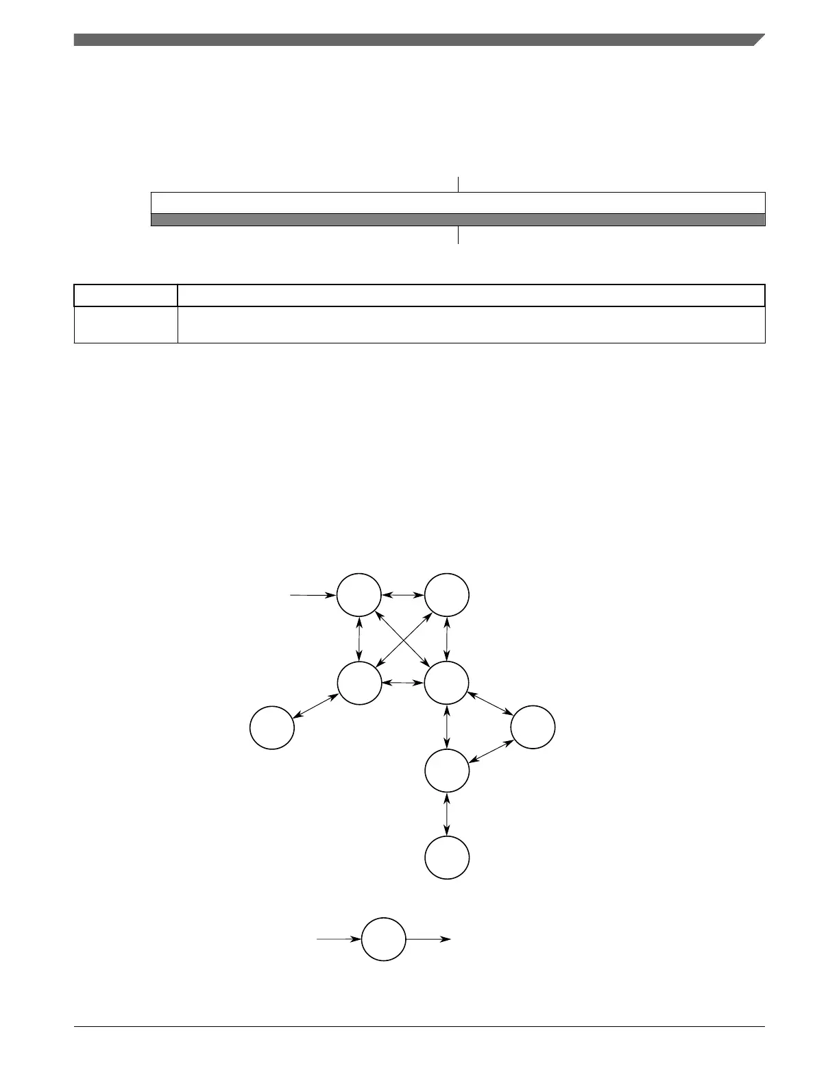
25.4.1 MCG mode state diagram
The nine states of the MCG are shown in the following figure and are described in Table
25-3. The arrows indicate the permitted MCG mode transitions.
FEEFEI
Reset
BLPI
FBI FBE
BLPE
PBE
PEE
Stop
Returns to the state that was active before
the MCU entered Stop mode, unless a
reset occurs while in Stop mode.
Entered from any state when
the MCU enters Stop mode
Figure 25-2. MCG mode state diagram
Chapter 25 Multipurpose Clock Generator (MCG)
K22F Sub-Family Reference Manual, Rev. 4, 08/2016
NXP Semiconductors 557

 Loading...