45.1.4.4 External Stop Mode
External Stop mode is used for chip power management. The module supports the
Peripheral Bus Stop mode mechanism. When a request is made to enter External Stop
mode, it acknowledges the request and completes the transfer that is in progress. When
the module reaches the frame boundary, it signals that the protocol clock to the module
may be shut off.
45.1.4.5 Debug Mode
Debug mode is used for system development and debugging. The MCR[FRZ] bit controls
module behavior in the Debug mode:
• If the bit is set, the module stops all serial transfers, when the chip is in debug mode.
• If the bit is cleared, the chip debug mode has no effect on the module.
45.2
Module signal descriptions
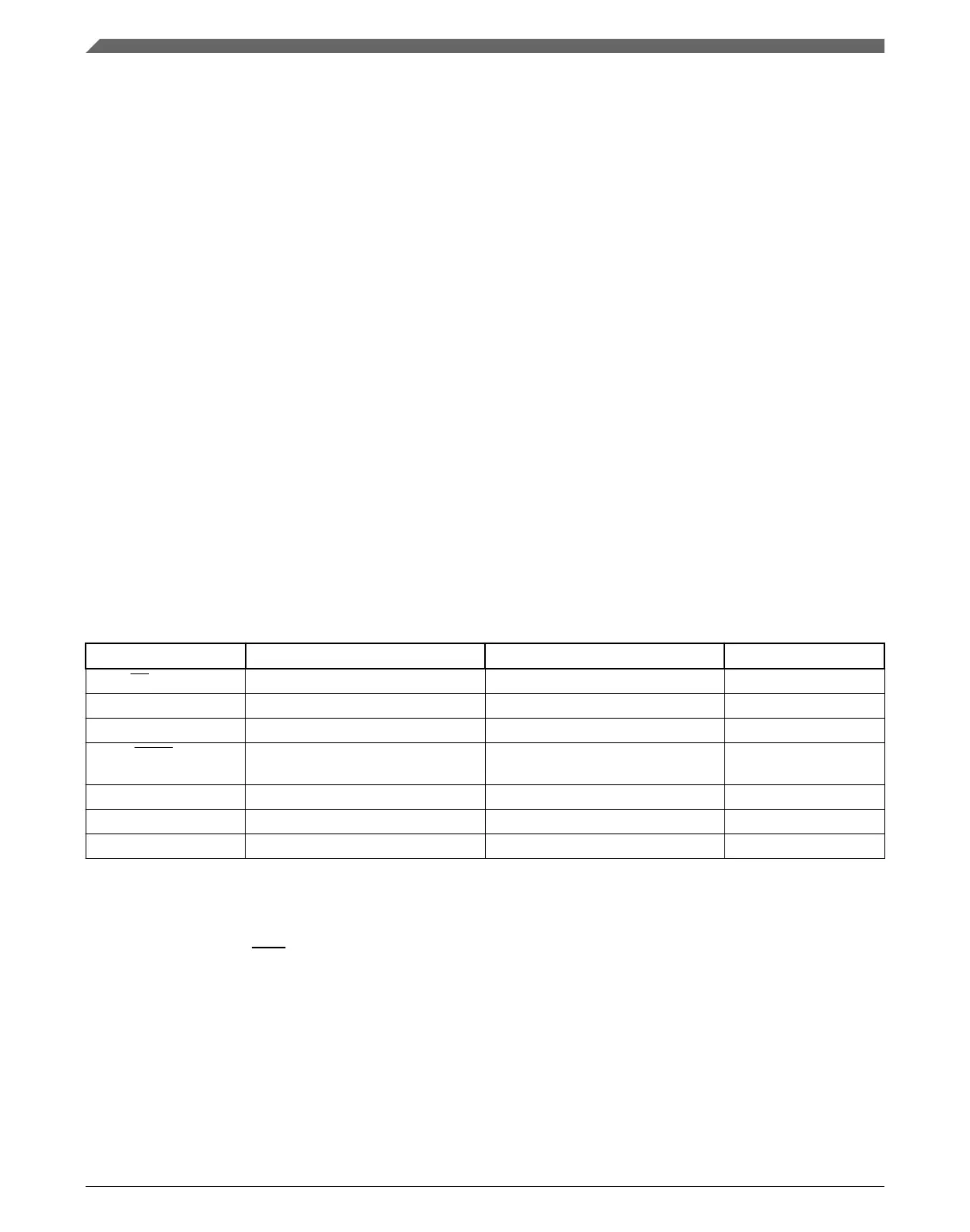
This table describes the signals on the boundary of the module that may connect off chip
(in alphabetical order).
Table 45-1. Module signal descriptions
Signal Master mode Slave mode I/O
PCS0/SS Peripheral Chip Select 0 (O) Slave Select (I) I/O
PCS[1:3] Peripheral Chip Selects 1–3 (Unused) O
PCS4 Peripheral Chip Select 4 (Unused) O
PCS5/ PCSS Peripheral Chip Select 5 /Peripheral
Chip Select Strobe
(Unused) O
SCK Serial Clock (O) Serial Clock (I) I/O
SIN Serial Data In Serial Data In I
SOUT Serial Data Out Serial Data Out O
45.2.1 PCS0/SS—Peripheral Chip Select/Slave Select
Master mode: Peripheral Chip Select 0 (O)—Selects an SPI slave to receive data
transmitted from the module.
Slave mode: Slave Select (I)—Selects the module to receive data transmitted from an SPI
master.
Module signal descriptions
K22F Sub-Family Reference Manual, Rev. 4, 08/2016
1128 NXP Semiconductors

 Loading...