TOF bit
...
7
8 8
7 7 7
6 6 6
5 5 54 43 3
2 21
0
1
...
previous value
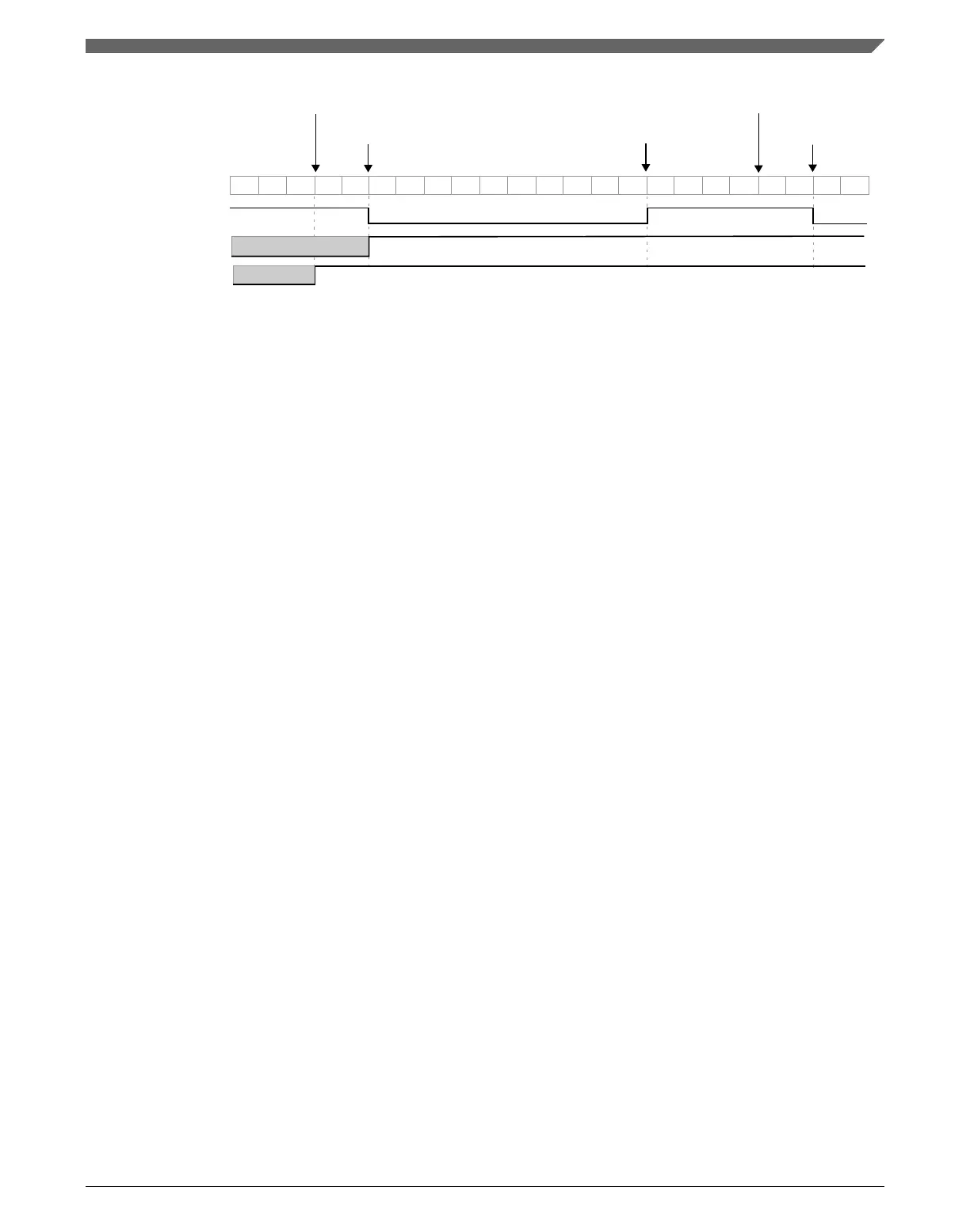
CNT
channel (n) output
counter
overflow
channel (n) match in
down counting
channel (n) match in
up counting
channel (n) match in
down counting
counter
overflow
CHnF bit
MOD = 0x0008
CnV = 0x0005
Figure 39-24. CPWM signal with ELSnB:ELSnA = X:1
If (CnV = 0x0000) or CnV is a negative value, that is (CnV[15] = 1), then the channel (n)
output is a 0% duty cycle CPWM signal and CHnF bit is not set even when there is the
channel (n) match.
If CnV is a positive value, that is (CnV[15] = 0), (CnV ≥ MOD), and (MOD ≠ 0x0000),
then the channel (n) output is a 100% duty cycle CPWM signal and CHnF bit is not set
even when there is the channel (n) match. This implies that the usable range of periods
set by MOD is 0x0001 through 0x7FFE, 0x7FFF if you do not need to generate a 100%
duty cycle CPWM signal. This is not a significant limitation because the resulting period
is much longer than required for normal applications.
The CPWM mode must not be used when the FTM counter is a free running counter.
39.4.8
Combine mode
The Combine mode is selected when:
• QUADEN = 0
• DECAPEN = 0
• COMBINE = 1, and
• CPWMS = 0
In Combine mode, an even channel (n) and adjacent odd channel (n+1) are combined to
generate a PWM signal in the channel (n) output.
In the Combine mode, the PWM period is determined by (MOD − CNTIN + 0x0001) and
the PWM pulse width (duty cycle) is determined by (|C(n+1)V − C(n)V|).
The CHnF bit is set and the channel (n) interrupt is generated (if CHnIE = 1) at the
channel (n) match (FTM counter = C(n)V). The CH(n+1)F bit is set and the channel (n
+1) interrupt is generated, if CH(n+1)IE = 1, at the channel (n+1) match (FTM counter =
C(n+1)V).
Chapter 39 FlexTimer Module (FTM)
K22F Sub-Family Reference Manual, Rev. 4, 08/2016
NXP Semiconductors 963

 Loading...