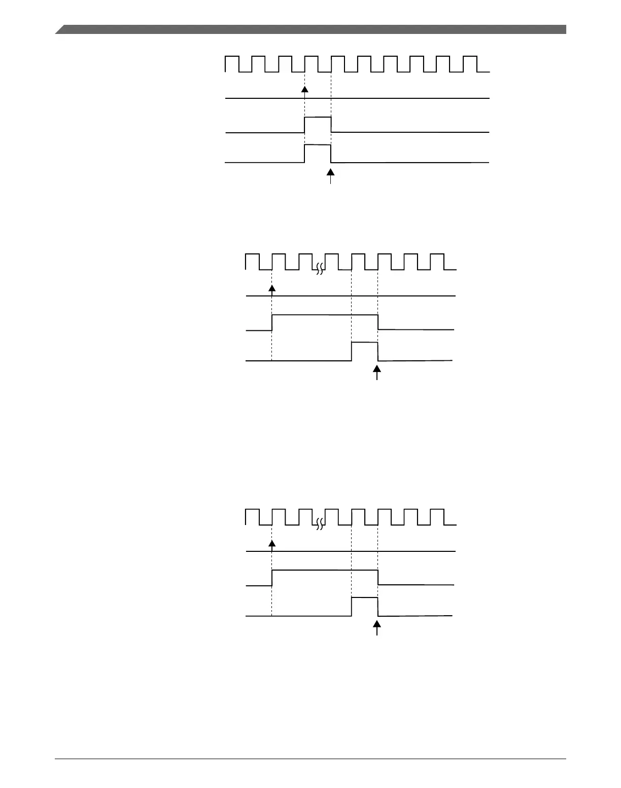
system clock
FTM counter is updated with the CNTIN register value
and channel outputs are forced to their initial value
write 1 to SWSYNC bit
SWSYNC bit
software trigger event
Figure 39-60. FTM counter synchronization with (SYNCMODE = 0), (REINIT = 1),
(PWMSYNC = 0), and software trigger was used
system clock
write 1 to TRIG0 bit
TRIG0 bit
trigger 0 event
FTM counter is updated with the CNTIN register value
and channel outputs are forced to their initial value
Figure 39-61. FTM counter synchronization with (SYNCMODE = 0), (HWTRIGMODE = 0),
(REINIT = 1), (PWMSYNC = 0), and a hardware trigger was used
If (SYNCMODE = 0), (REINIT = 1), and (PWMSYNC = 1) then this synchronization is
made on the next enabled hardware trigger. The TRIGn bit is cleared according to
Hardware trigger.
system clock
write 1 to TRIG0 bit
TRIG0 bit
trigger 0 event
FTM counter is updated with the CNTIN register value
and channel outputs are forced to their initial value
Figure 39-62. FTM counter synchronization with (SYNCMODE = 0), (HWTRIGMODE = 0),
(REINIT = 1), (PWMSYNC = 1), and a hardware trigger was used
Functional description
K22F Sub-Family Reference Manual, Rev. 4, 08/2016
988 NXP Semiconductors

 Loading...