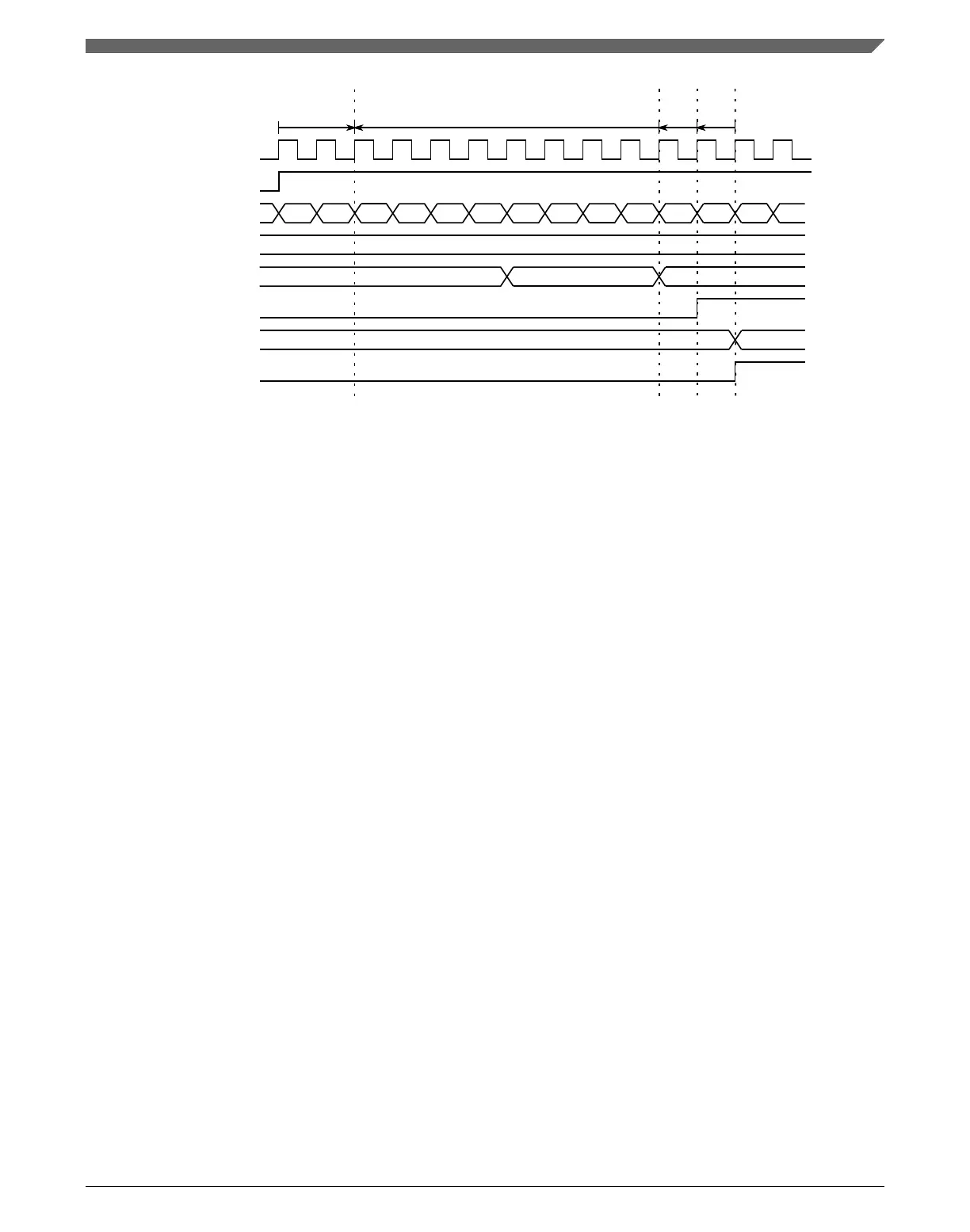
system clock
channel (n) input
FTM counter
CHnFVAL[3:0]
filter counter
C(n)V
CHnF
1 2 3 4 5 6 7 8 9 10 11 12
13
2
1 2 1
0 12
filter output
synchronizer delay filter counter delay
filter
output
delay
edge
detector
delay
Figure 39-14. Input capture example
39.4.4.2 FTM Counter Reset in Input Capture Mode
If the channel (n) is in input capture mode and FTMx_CnSC [ICRST = 1], then when the
selected input capture event occurs in the channel (n) input signal, the current value of the
FTM counter is captured into the CnV register, the CHnF bit is set, the channel (n)
interrupt is generated (if CHnIE = 1) and the FTM counter is reset to the CNTIN register
value.
This allows the FTM to measure a period/pulse being applied to FTM_CHn ( counts of
the FTM clock input) without having to implement a subtraction calculation in software
subsequent to the event occurring.
The figure below shows the FTM counter reset when the selected input capture event is
detected in a channel in input capture mode with ICRST = 1.
Chapter 39 FlexTimer Module (FTM)
K22F Sub-Family Reference Manual, Rev. 4, 08/2016
NXP Semiconductors 957

 Loading...