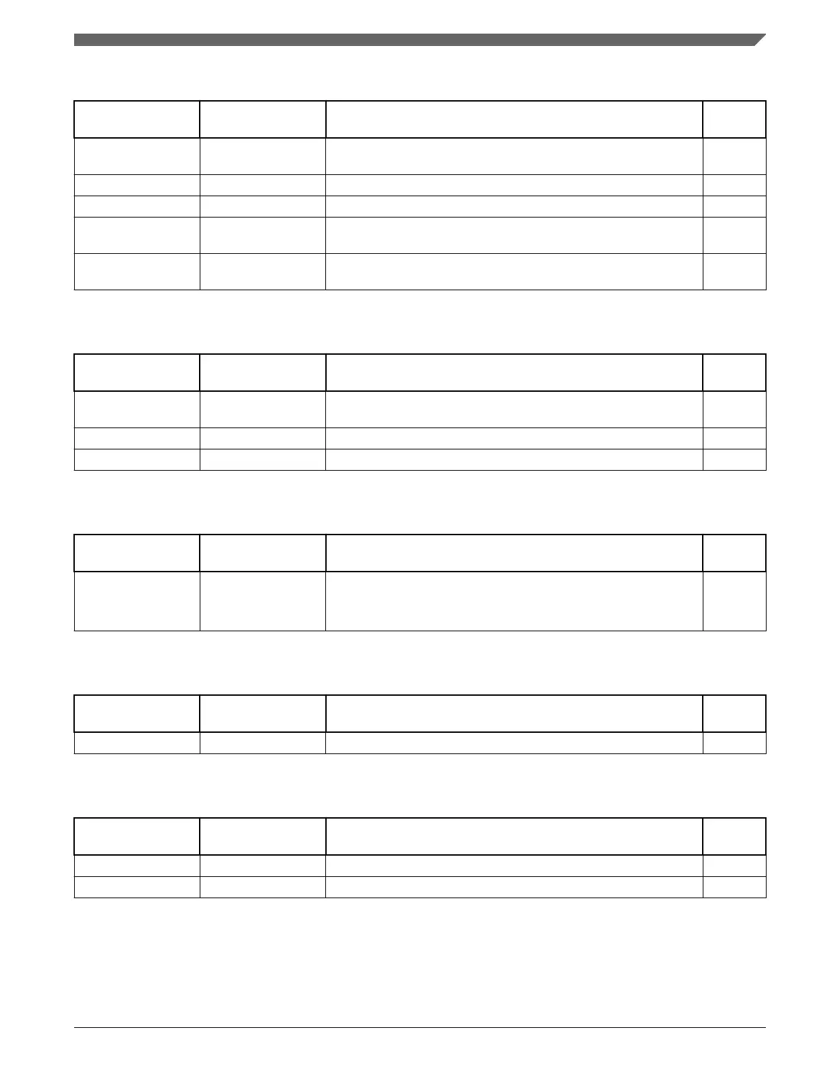
Table 10-20. FTM 2 Signal Descriptions
Chip signal name Module signal
name
Description I/O
FTM_CLKIN[1:0] EXTCLK External clock. FTM external clock can be selected to drive the
FTM counter.
I
FTM2_CH[1:0] CHn FTM channel (n), where n can be 7-0 I/O
FTM2_FLT0 FAULTj Fault input (j), where j can be 3-0 I
FTM2_QD_PHA PHA Quadrature decoder phase A input. Input pin associated with
quadrature decoder phase A.
I
FTM2_QD_PHB PHB Quadrature decoder phase B input. Input pin associated with
quadrature decoder phase B.
I
Table 10-21. FTM 3 Signal Descriptions
Chip signal name Module signal
name
Description I/O
FTM_CLKIN[1:0] EXTCLK External clock. FTM external clock can be selected to drive the
FTM counter.
I
FTM3_CH[7:0] CHn FTM channel (n), where n can be 7-0 I/O
FTM3_FLT0 FAULTj Fault input (j), where j can be 3-0 I
Table 10-22. PDB 0 Signal Descriptions
Chip signal name Module signal
name
Description I/O
PDB0_EXTRG EXTRG External Trigger Input Source
If the PDB is enabled and external trigger input source is selected,
a positive edge on the EXTRG signal resets and starts the counter.
I
Table 10-23. LPTMR 0 Signal Descriptions
Chip signal name Module signal
name
Description I/O
LPTMR0_ALT[:1] LPTMR0_ALTn Pulse Counter Input pin I
Table 10-24. RTC Signal Descriptions
Chip signal name Module signal
name
Description I/O
VBAT — Backup battery supply for RTC and VBAT register file I
RTC_CLKOUT RTC_CLKOUT 1 Hz square-wave output or OSCERCLK O
Chapter 10 Signal Multiplexing and Signal Descriptions
K22F Sub-Family Reference Manual, Rev. 4, 08/2016
NXP Semiconductors 235

 Loading...