when the second rising edge is detected, that is, the edge selected by ELS(n+1)B:ELS(n
+1)A bits. The CH(n+1)F bit indicates when two edges of the period were captured and
the C(n)V and C(n+1)V registers are ready for reading.
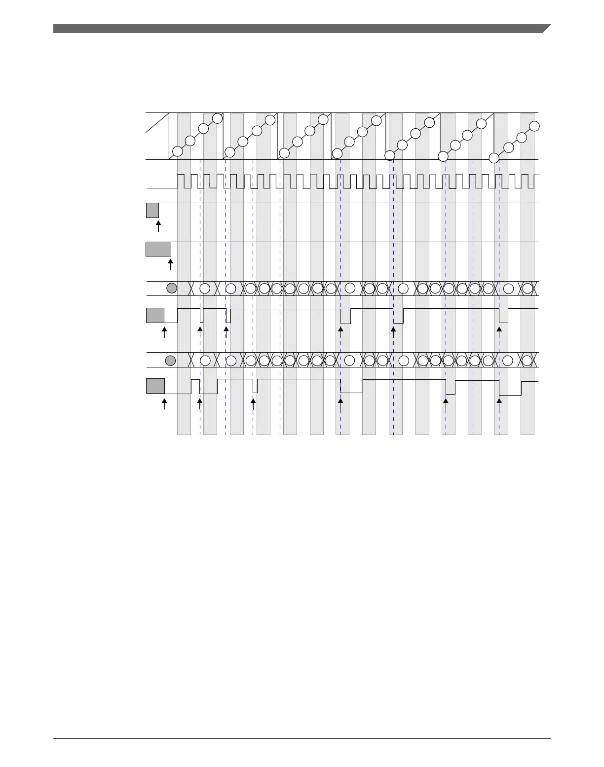
channel (n) input
(after the filter
DECAPEN bit
C(n+1)V
FTM counter
clear CH(n+1)F
2
1
2
3
channel input)
DECAP bit
set DECAPEN
set DECAP
5
6
7
8
10
3
4
6
5
Note
- The commands set DECAPEN, set DECAP, clear CH(n)F, and clear CH(n+1)F are made by the user.
4
9
11
12
13
14
9
10
7
15
16
17
18
19
20
22
23
24
26
27
28
15
16
21
C(n)V
CH(n+1)F bit
CH(n)F bit
clear CH(n)F
1
8
12
22
24
11
19
21
23
25 27
23
20
19
17
7
9
11
13
15
6
8
10
12
1614
24
22
20
18
26
25
21
Figure 39-87. Dual Edge Capture – Continuous mode to measure of the period between
two consecutive rising edges
39.4.24.5
Read coherency mechanism
The Dual Edge Capture mode implements a read coherency mechanism between the
FTM counter value captured in C(n)V and C(n+1)V registers. The read coherency
mechanism is illustrated in the following figure. In this example, the channels (n) and (n
+1) are in Dual Edge Capture – Continuous mode for positive polarity pulse width
measurement. Thus, the channel (n) is configured to capture the FTM counter value when
there is a rising edge at channel (n) input signal, and channel (n+1) to capture the FTM
counter value when there is a falling edge at channel (n) input signal.
Chapter 39 FlexTimer Module (FTM)
K22F Sub-Family Reference Manual, Rev. 4, 08/2016
NXP Semiconductors 1013

 Loading...