Table 39-16. When possible loading points are enabled
Loading point Enabled
When the FTM counter wraps from MOD value to CNTIN
value
Always
At the channel (j) match (FTM counter = C(j)V) When CHjSEL = 1
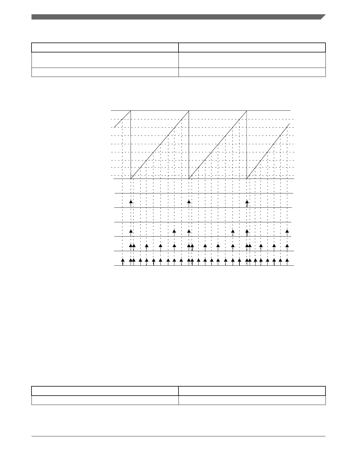
The following figure shows some examples of enabled loading points.
NOTE
(c)
(a) LDOK = 0, CH0SEL = 0, CH1SEL = 0, CH2SEL = 0, CH3SEL = 0, CH4SEL = 0, CH5SEL = 0, CH6SEL = 0, CH7SEL = 0
(b) LDOK = 1, CH0SEL = 0, CH1SEL = 0, CH2SEL = 0, CH3SEL = 0, CH4SEL = 0, CH5SEL = 0, CH6SEL = 0, CH7SEL = 0
(c) LDOK = 0, CH0SEL = 0, CH1SEL = 0, CH2SEL = 0, CH3SEL = 1, CH4SEL = 0, CH5SEL = 0, CH6SEL = 0, CH7SEL = 0
(d) LDOK = 1, CH0SEL = 0, CH1SEL = 0, CH2SEL = 0, CH3SEL = 0, CH4SEL = 0, CH5SEL = 0, CH6SEL = 1, CH7SEL = 0
(e) LDOK = 1, CH0SEL = 1, CH1SEL = 0, CH2SEL = 1, CH3SEL = 0, CH4SEL = 1, CH5SEL = 0, CH6SEL = 1, CH7SEL = 0
(f) LDOK = 1, CH0SEL = 1, CH1SEL = 1, CH2SEL = 1, CH3SEL = 1, CH4SEL = 1, CH5SEL = 1, CH6SEL = 1, CH7SEL = 1
(d)
(e)
(f)
(b)
(a)
FTM counter = MOD
FTM counter = C7V
FTM counter = C6V
FTM counter = C5V
FTM counter = C4V
FTM counter = C3V
FTM counter = C2V
FTM counter = C1V
FTM counter = C0V
Figure 39-96. Loading points for intermediate load
After enabling the loading points, the LDOK bit must be set for the load to occur. In this
case, the load occurs at the next enabled loading point according to the following
conditions:
Table 39-17. Conditions for loads occurring at the next enabled loading point
When a new value was written Then
To the MOD register The MOD register is updated with its write buffer value.
Table continues on the next page...
Chapter 39 FlexTimer Module (FTM)
K22F Sub-Family Reference Manual, Rev. 4, 08/2016
NXP Semiconductors 1021

 Loading...