Master
mode?
Tx/Rx?
Arbitration
lost?
IAAS=1?
Tx/Rx?
ACK from
receiver?
SRW=1?
IAAS=1?
Clear ARBL
2nd to
last byte to be
read?
Last byte
to be read?
RXAK=0?
Last byte
transmitted?
End of
address cycle
(master Rx)?
Write next
byte to Data reg
Generate stop
signal (MST=0)
Read data from
Data reg
and soft CRC
Transmit
next byte
RTI
Switch to
Rx mode
Switch to
Rx mode
Dummy read
from Data reg
Generate stop
signal (MST=0)
Read data from
Data reg
and store
Read data from
Data reg
and store (note 3)
Dummy read
from Data reg
N
Y
N
N
N
N
N
N
Y
Y
Y
Y
Y
(read)
N (write)
N
Y
RxTx
Rx
Tx
Y
N
Address transfer
(see note 1)
N
Y
Y
Y
SLTF=1 or
SHTF2=1?
N
Y
Clear IICIF
FACK=1?
N
Y
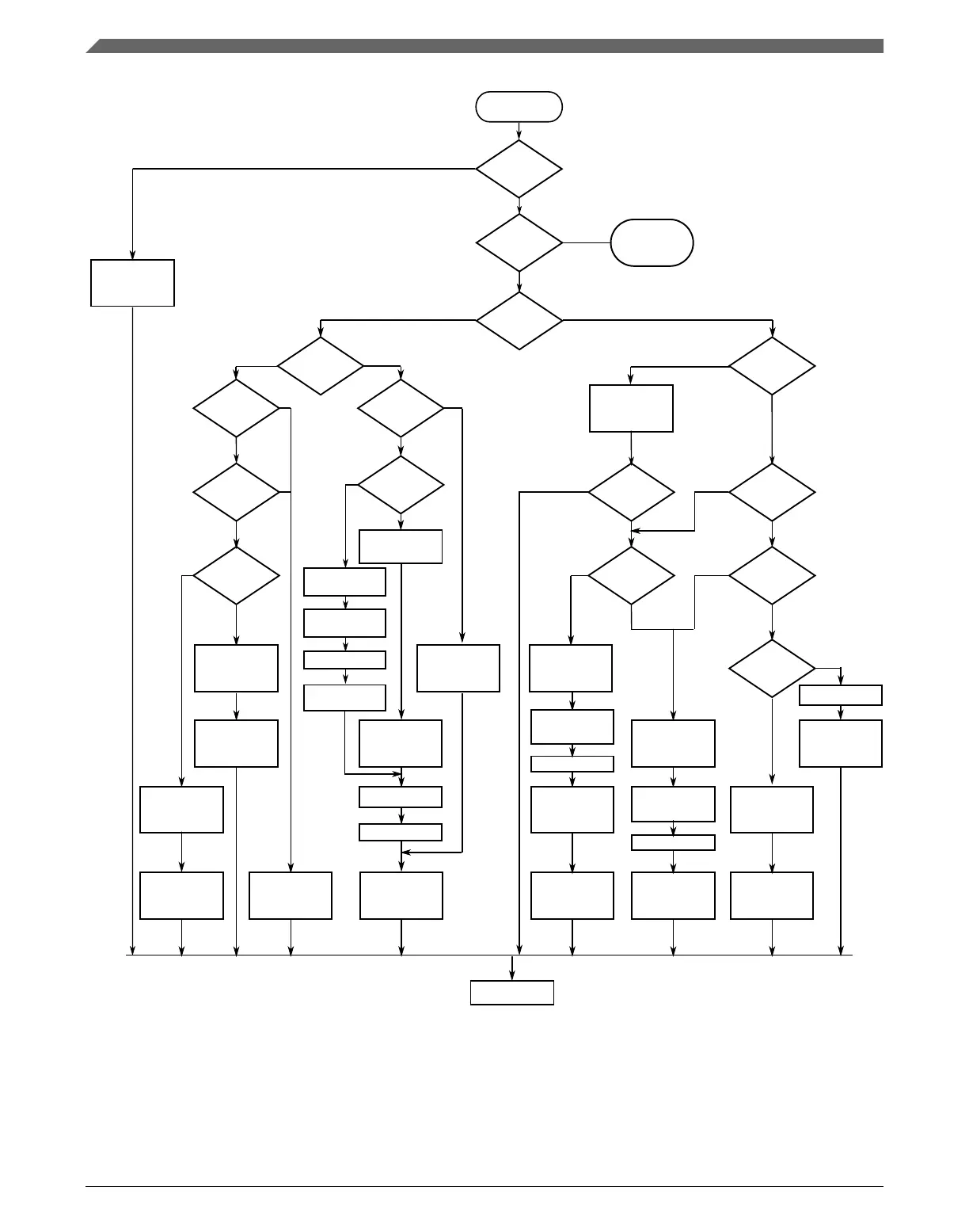
See typical I2C
interrupt routine
flow chart
Set TXAK to
proper value
Clear IICIF
Set Tx mode
Write data
to Data reg
Clear IICIF
Notes:
1. If general call or SIICAEN is enabled, check to determine if the received address is a general call address (0x00) or an SMBus
device default address. In either case, they must be handled by user software.
2. In receive mode, one bit time delay may be needed before the first and second data reading, to wait for the possible longest time
period (in worst case) of the 9th SCL cycle.
3. This read is a dummy read in order to reset the SMBus receiver state machine.
Clear IICIF
Read data from
Data reg
and soft CRC
Read data from
Data reg
and soft CRC
Set TXAK=1,
Clear FACK=0
Read data and
Soft CRC
Set TXAK to
proper value
Delay (note 2)
Delay (note 2)
Delay (note 2)
Entry of ISR
Delay (note 2)
Set TXAK to
proper value,
Clear IICIF
Set TXAK to
proper value,
Clear IICIF
Figure 46-7. Typical I2C SMBus interrupt routine
Initialization/application information
K22F Sub-Family Reference Manual, Rev. 4, 08/2016
1214 NXP Semiconductors

 Loading...