SHIFT DIRECTION
PARITY
GENERATION
PE
PT
TRANSMITTER CONTROL
M
MSBF
INTERNAL BUS
Tx port en
Tx input buffer en
Tx output buffer en
STOP
TXINV
TxD Pin Control
START
BAUDRATE GENERATE
MODULE
CLOCK
SBR12:0
BRFA4:0
VARIABLE 12-BIT TRANSMIT
SHIFT REGISTER
M10
R485 CONTROL
RTS_B
CTS_B
TXDIR
SBK
TE
DMA Done
7816 LOGIC
TxD
IRQ / DMA
LOGIC
INFRARED LOGIC
DMA Requests
IRQ Requests
TxD
LOOP
CONTROL
LOOPS
RSRC
UART DATA REGISTER (UART_D)
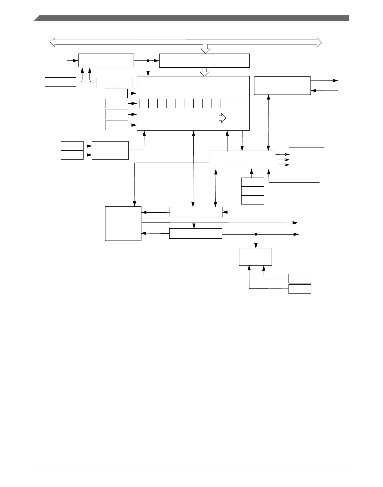
Figure 47-1. Transmitter Block Diagram
47.4.1.1
Transmitter character length
The UART transmitter can accommodate either 8, 9, or 10-bit data characters. The state
of the C1[M] and C1[PE] bits and the C4[M10] bit determine the length of data
characters. When transmitting 9-bit data, bit C3[T8] is the ninth bit (bit 8).
Functional description
K22F Sub-Family Reference Manual, Rev. 4, 08/2016
1260 NXP Semiconductors

 Loading...