M
PE
PT
RE
VARIABLE 12-BIT RECEIVE
STOP
START
RECEIVE
WAKEUP
DATA BUFFER
INTERNAL BUS
MODULE
SBR12:0
BAUDRATE
CLOCK
RAF
LOGIC
SHIFT DIRECTION
ACTIVE EDGE
DETECT
LBKDE
BRFA4:0
MSBF
GENERATOR
SHIFT REGISTER
M10
RXINV
IRQ / DMA
LOGIC
DMA Requests
IRQ Requests
PARITY
LOGIC
CONTROL
RxD
RxD
LOOPS
RSRC
From Transmitter
RECEIVER
SOURCE
CONTROL
7816 LOGIC
To TxD
INFRARED LOGIC
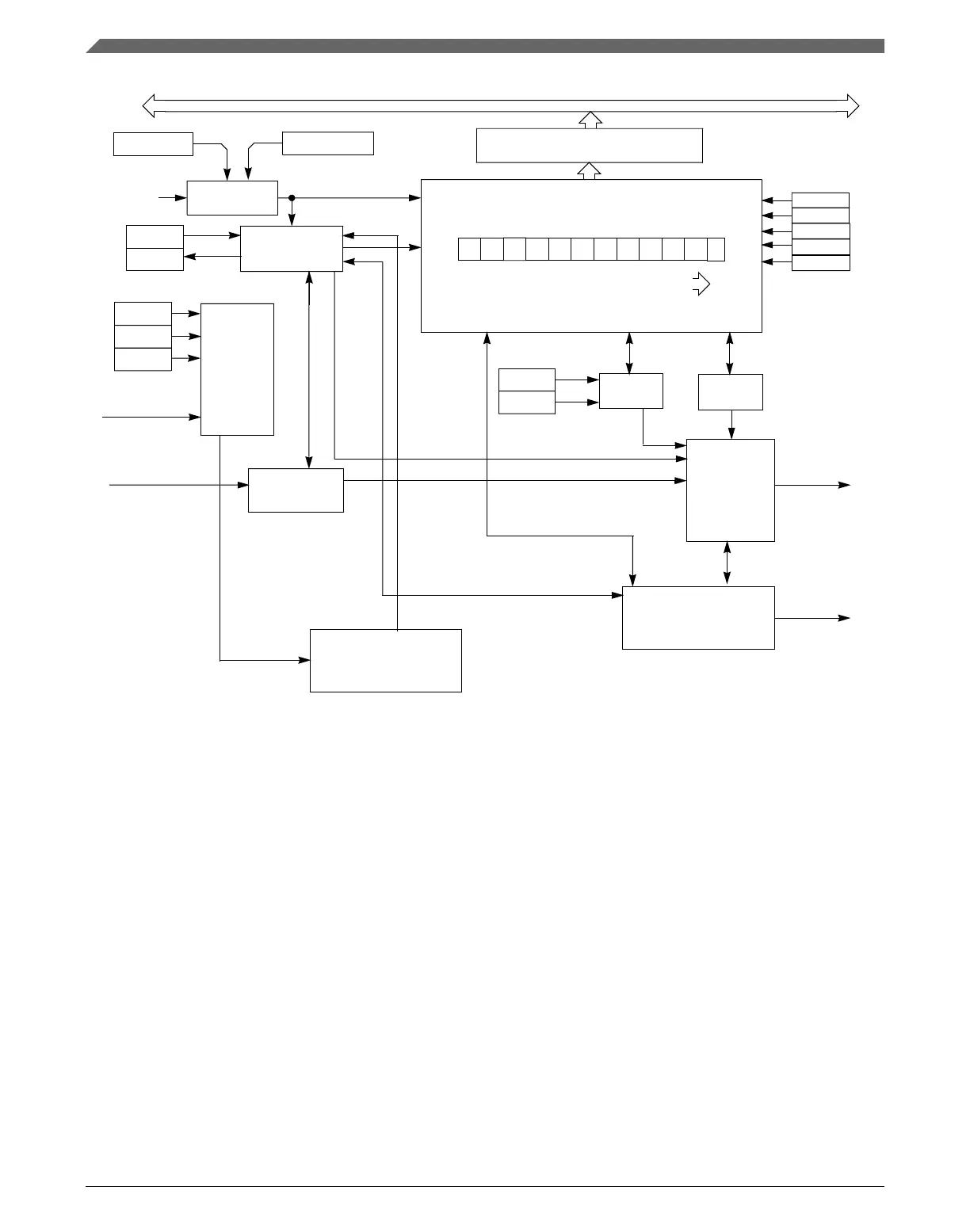
Figure 47-3. UART receiver block diagram
47.4.2.1
Receiver character length
The UART receiver can accommodate 8-, 9-, or 10-bit data characters. The states of
C1[M], C1[PE] and C4[M10] determine the length of data characters. When receiving 9
or 10-bit data, C3[R8] is the ninth bit (bit 8).
47.4.2.2
Receiver bit ordering
When S2[MSBF] is set, the receiver operates such that the first bit received after the start
bit is the MSB of the dataword. Similarly, the bit received immediately preceding the
parity bit, or the stop bit if parity is not enabled, is treated as the LSB for the dataword.
All necessary bit ordering is handled automatically by the module. Therefore, the format
of the data read from receive data buffer is completely independent of S2[MSBF].
Functional description
K22F Sub-Family Reference Manual, Rev. 4, 08/2016
1266 NXP Semiconductors

 Loading...