RECEIVER
RT CLOCK
STOP
IDLE OR NEXT FRAME
DATA
SAMPLES
RT16
RT15
RT14
RT13
RT12
RT11
RT10
RT9
RT8
RT7
RT6
RT5
RT4
RT3
RT2
RT1
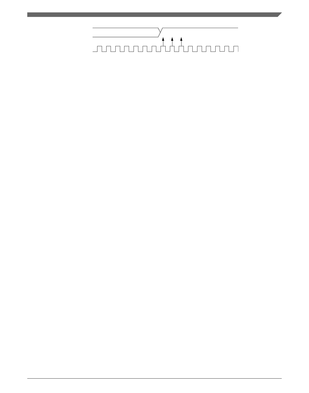
Figure 47-13. Fast data
For an 8-bit data character, data sampling of the stop bit takes the receiver 154 RT cycles
(9 bit times × 16 RT cycles + 10 RT cycles).
With the misaligned character shown in the Figure 47-13, the receiver counts 154 RT
cycles at the point when the count of the transmitting device is 160 RT cycles (10 bit
times × 16 RT cycles).
The maximum percent difference between the receiver count and the transmitter count of
a fast 8-bit character with no errors is:
((154 − 160) ÷ 154) × 100 = 3.90%
For a 9-bit data character, data sampling of the stop bit takes the receiver 170 RT cycles
(10 bit times × 16 RT cycles + 10 RT cycles).
With the misaligned character shown in the Figure 47-13, the receiver counts 170 RT
cycles at the point when the count of the transmitting device is 176 RT cycles (11 bit
times × 16 RT cycles).
The maximum percent difference between the receiver count and the transmitter count of
a fast 9-bit character with no errors is:
((170 − 176) ÷ 170) × 100 = 3.53%
47.4.2.10
Receiver wakeup
C1[WAKE] determines how the UART is brought out of the standby state to process an
incoming message. C1[WAKE] enables either idle line wakeup or address mark wakeup.
Receiver wakeup is not supported when C7816[ISO_7816E] is set/enabled because
multi-receiver systems are not allowed.
47.4.2.10.1
Idle input line wakeup (C1[WAKE] = 0)
In this wakeup method, an idle condition on the unsynchronized receiver input signal
clears C2[RWU] and wakes the UART. The initial frame or frames of every message
contain addressing information. All receivers evaluate the addressing information, and
Chapter 47 Universal Asynchronous Receiver/Transmitter (UART)
K22F Sub-Family Reference Manual, Rev. 4, 08/2016
NXP Semiconductors 1277

 Loading...