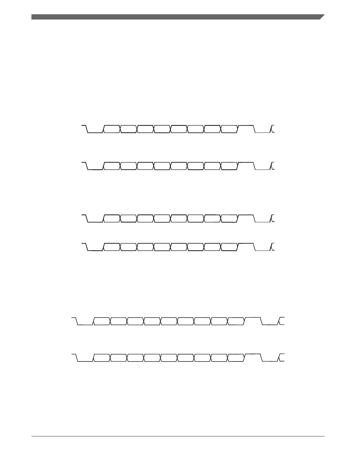
47.4.4.3 Timing examples
Timing examples of these configurations in the NRZ mark/space data format are
illustrated in the following figures. The timing examples show all of the configurations in
the following sub-sections along with the LSB and MSB first variations.
47.4.4.3.1 Eight-bit format with parity disabled
The most significant bit can be used for address mark wakeup.
BIT 0 BIT 1 BIT 2 BIT 3 BIT 4 BIT 5 BIT 6 BIT 7
STOP
BIT
ADDRESS
MARK
START
BIT
START
BIT
Figure 47-14. Eight bits of data with LSB first
BIT 7 BIT 6 BIT 5 BIT 4 BIT 3 BIT 2 BIT 1 BIT 0
STOP
BIT
ADDRESS
MARK
START
BIT
START
BIT
Figure 47-15. Eight bits of data with MSB first
47.4.4.3.2 Eight-bit format with parity enabled
BIT 0 BIT 1 BIT 2 BIT 3 BIT 4 BIT 5 BIT 6
STOP
BIT
START
BIT
START
BIT
PARITY
Figure 47-16. Seven bits of data with LSB first and parity
BIT 6 BIT 5 BIT 4 BIT 3 BIT 2 BIT 1 BIT 0
STOP
BIT
START
BIT
START
BIT
PARITY
Figure 47-17. Seven bits of data with MSB first and parity
47.4.4.3.3
Nine-bit format with parity disabled
The most significant bit can be used for address mark wakeup.
BIT 0 BIT 1 BIT 2 BIT 3 BIT 4 BIT 5 BIT 6 BIT 7
BIT 8
STOP
BIT
ADDRESS
MARK
START
BIT
START
BIT
Figure 47-18. Nine bits of data with LSB first
BIT 8 BIT 7 BIT 6 BIT 5 BIT 4 BIT 3 BIT 2 BIT 1
BIT 0
STOP
BIT
ADDRESS
MARK
START
BIT
START
BIT
Figure 47-19. Nine bits of data with MSB first
47.4.4.3.4
Nine-bit format with parity enabled
Chapter 47 Universal Asynchronous Receiver/Transmitter (UART)
K22F Sub-Family Reference Manual, Rev. 4, 08/2016
NXP Semiconductors 1283

 Loading...