2. UART0 and UART1 are clocked from the core clock, the remaining UARTs are
clocked on the bus clock. The maximum baud rate is 1/16 of related source clock
frequency.
3. IrDA is available on all UARTs
4. UART0 contains the standard features plus ISO7816
5. UART0 contains 8-entry transmit and 8-entry receive FIFOs
6. All other UARTs contain a 1-entry transmit and receive FIFOs
3.9.4.2 UART wakeup
The UART can be configured to generate an interrupt/wakeup on the first active edge that
it receives.
3.9.4.3 UART interrupts
The UART has multiple sources of interrupt requests. However, some of these sources
are OR'd together to generate a single interrupt request. See below for the mapping of the
individual interrupt sources to the interrupt request:
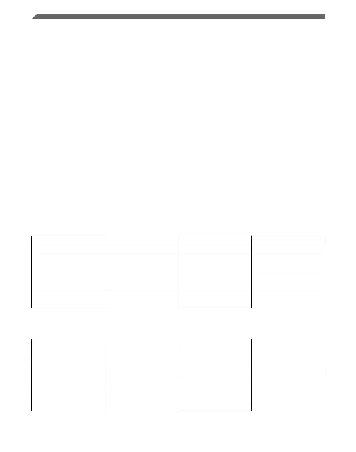
The status interrupt combines the following interrupt sources:
Source UART 0 UART 1 UART 2
Transmit data empty x x x
Transmit complete x x x
Idle line x x x
Receive data full x x x
LIN break detect x x x
RxD pin active edge x x x
Initial character detect x — —
The error interrupt combines the following interrupt sources:
Source UART 0 UART 1 UART 2
Receiver overrun x x x
Noise flag x x x
Framing error x x x
Parity error x x x
Transmitter buffer overflow x x x
Receiver buffer overflow x x x
Receiver buffer underflow x x x
Table continues on the next page...
Communication interfaces
K22F Sub-Family Reference Manual, Rev. 4, 08/2016
132 NXP Semiconductors

 Loading...