WAIT
STOP
RUN
LLS
VLLS
VLPS
VLPR
VLPW
Any RESET
HSRUN
4
6
7
3
1
2
8
10
11
9
5
12
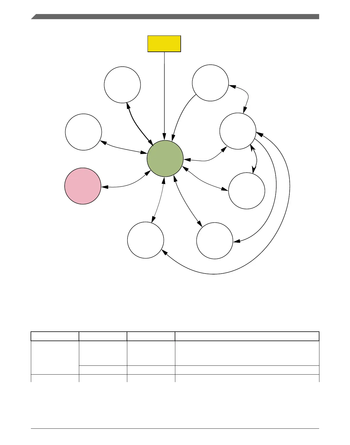
Figure 15-1. Power mode state diagram
The following table defines triggers for the various state transitions shown in the previous
figure.
Table 15-2. Power mode transition triggers
Transition # From To Trigger conditions
1 RUN WAIT Sleep-now or sleep-on-exit modes entered with SLEEPDEEP
clear, controlled in System Control Register in ARM core.
See note.
1
WAIT RUN Interrupt or Reset
2 RUN STOP PMCTRL[RUNM]=00, PMCTRL[STOPM]=000
2
Table continues on the next page...
Functional description
K22F Sub-Family Reference Manual, Rev. 4, 08/2016
360 NXP Semiconductors

 Loading...