Note
Because of the dynamic nature of the system (due to DMA
channel priorities, bus arbitration, interrupt service routine
lengths, etc.), the number of clock cycles between a trigger and
the actual DMA transfer cannot be guaranteed.
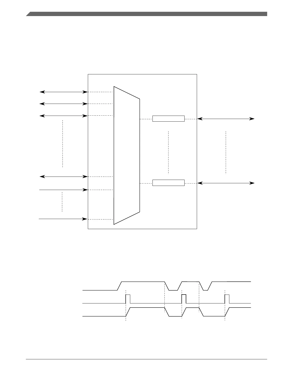
DMA channel #0
Source #1
Source #2
Source #3
Always #1
DMA channel #m-1
Always #y
Trigger #m
Source #x
Trigger #1
Figure 21-2. DMAMUX triggered channels
The DMA channel triggering capability allows the system to schedule regular DMA
transfers, usually on the transmit side of certain peripherals, without the intervention of
the processor. This trigger works by gating the request from the peripheral to the DMA
until a trigger event has been seen. This is illustrated in the following figure.
DMA request
Peripheral request
Trigger
Figure 21-3. DMAMUX channel triggering: normal operation
Functional description
K22F Sub-Family Reference Manual, Rev. 4, 08/2016
418 NXP Semiconductors

 Loading...