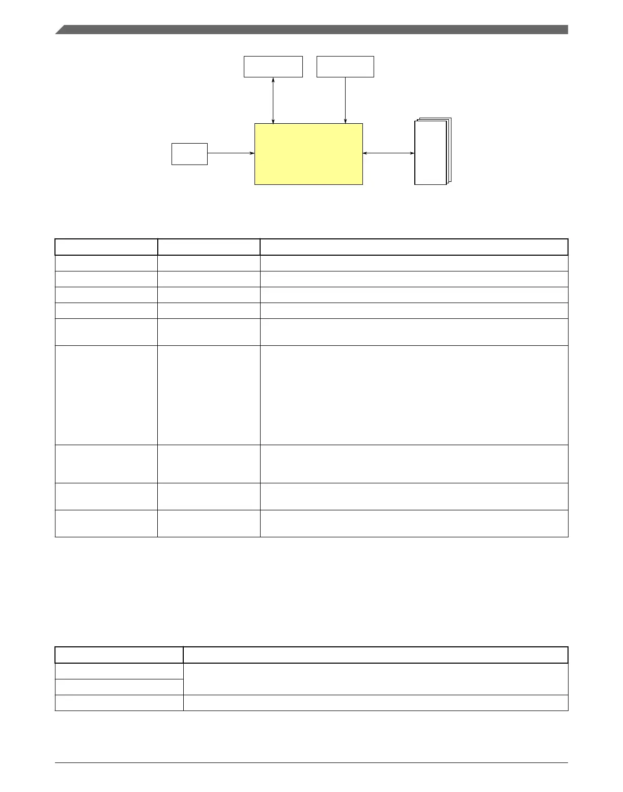
PPB
Modules
PPB
ARM Cortex-M4
Core
Debug
Interrupts
Crossbar
switch
Figure 3-1. Core configuration
Table 3-1. Reference links to related information
Topic Related module Reference
Full description ARM Cortex-M4 core ARM Cortex-M4 Technical Reference Manual
System memory map System memory map
Clocking Clock distribution
Power management Power management
System/instruction/data
bus module
Crossbar switch Crossbar switch
Debug IEEE 1149.1 JTAG
IEEE 1149.7 JTAG
(cJTAG)
Serial Wire Debug
(SWD)
ARM Real-Time Trace
Interface
Debug
Interrupts Nested Vectored
Interrupt Controller
(NVIC)
NVIC
Private Peripheral Bus
(PPB) module
Miscellaneous Control
Module (MCM)
MCM
Private Peripheral Bus
(PPB) module
Single-precision floating
point unit (FPU)
FPU
3.2.1.1 Buses, interconnects, and interfaces
The ARM Cortex-M4 core has four buses as described in the following table.
Bus name Description
Instruction code (ICODE) bus The ICODE and DCODE buses are muxed. This muxed bus is called the CODE bus and is
connected to the crossbar switch via a single master port.
Data code (DCODE) bus
System bus The system bus is connected to a separate master port on the crossbar.
Table continues on the next page...
Core modules
K22F Sub-Family Reference Manual, Rev. 4, 08/2016
58 NXP Semiconductors

 Loading...