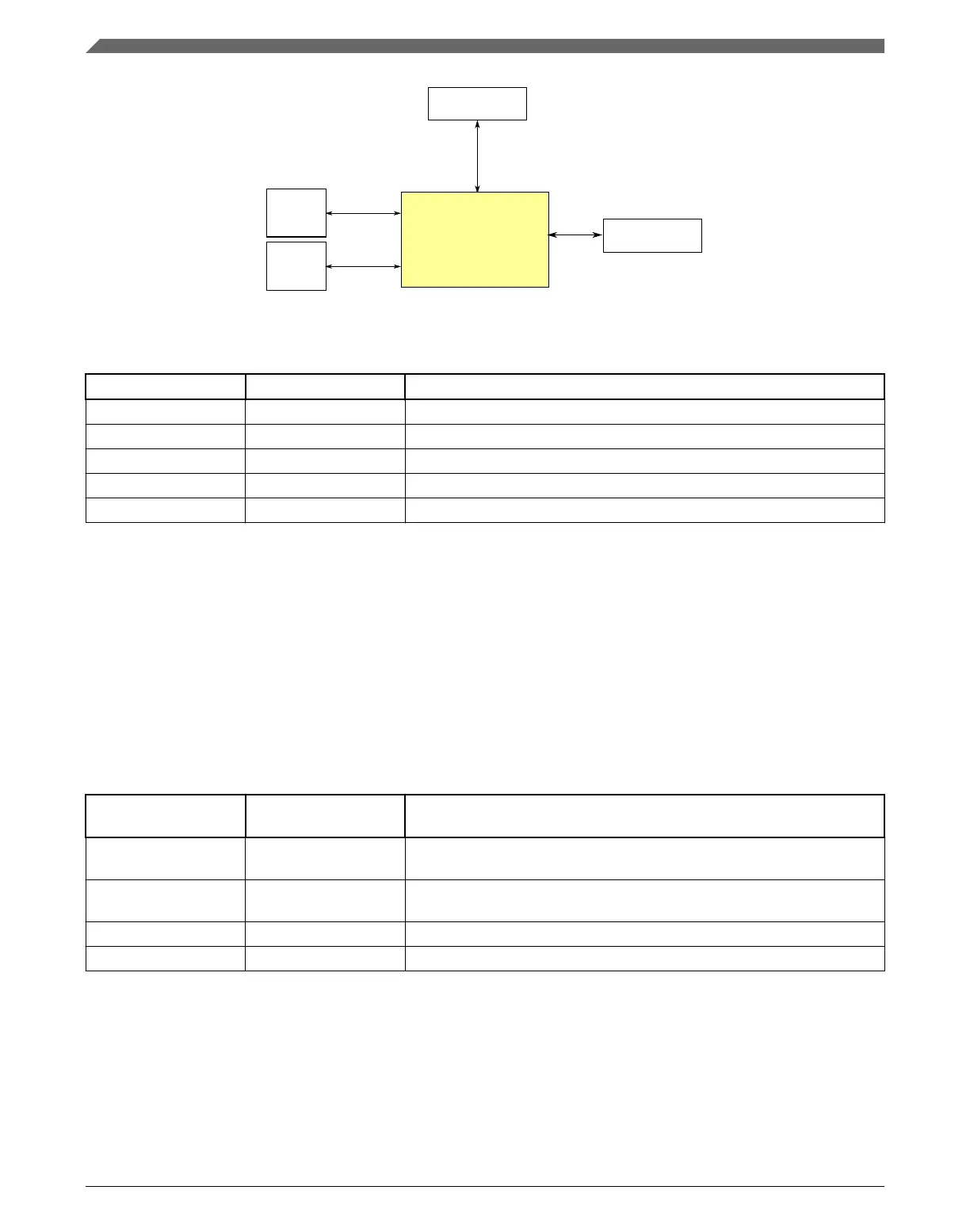
Register
access
Peripheral
bridge
Multipurpose Clock
Generator (MCG)
RTC
oscillator
System
oscillator
System integration
module (SIM)
Figure 3-16. MCG configuration
Table 3-27. Reference links to related information
Topic Related module Reference
Full description MCG MCG
System memory map System memory map
Clocking Clock distribution
Power management Power management
Signal multiplexing Port control Signal multiplexing
3.4.1.1 MCG oscillator clock input options
The MCG has multiple oscillator input clock sources. Within the context of the MCG
these are all referred to as the external reference clock and selection is determined by
MCG_C7[OSCSEL] bitfield. The following table shows the chip-specific clock
assignments for this bitfield.
Table 3-28. MCG Oscillator Reference Options
MCG_C7[OSCSEL] MCG defined
selection
Chip clock
00 OSCCLK0 - System
Oscillator
OSCCLK - Undivided system oscillator output. Derived from external
crystal circuit or directly from EXTAL.
01 OSC2/RTC Oscillator RTC 32kHz oscillator output. RTC clock is derived from external crystal
circuit associated with RTC.
10 OSCCLK1 - Oscillator IRC48MCLK. Derived from internal 48 MHz oscillator.
11 Reserved —
See Clock Distribution for more details on these clocks.
Clock modules
K22F Sub-Family Reference Manual, Rev. 4, 08/2016
82 NXP Semiconductors

 Loading...