For cases where a comparator is used to drive a fault input, for example, for a motor-
control module such as FTM, it must be configured to operate in Continuous mode so
that an external fault can immediately pass through the comparator to the target fault
circuitry.
Note
Filtering and sampling settings must be changed only after
setting CR1[SE]=0 and CR0[FILTER_CNT]=0x00. This resets
the filter to a known state.
35.3.1.1 Disabled mode (# 1)
In Disabled mode, the analog comparator is non-functional and consumes no power.
CMPO is 0 in this mode.
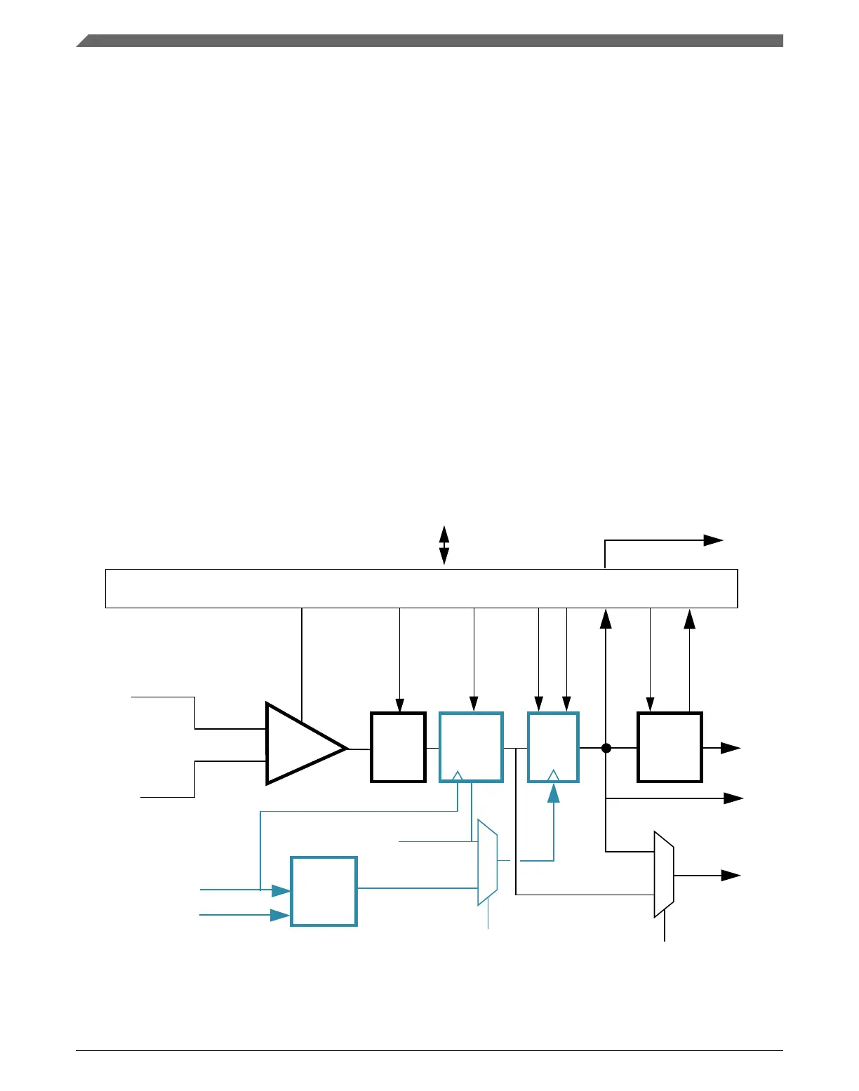
35.3.1.2 Continuous mode (#s 2A & 2B)
IRQ
Internal bus
INP
INM
FILTER_CNT
INV
COUT
COUT
OPE
SE
CMPO to
PAD
COUTA
1
WE
0
SE
CGMUX
COS
FILT_PER
0
+
-
FILT_PER
COS
IER/F CFR/F
WINDOW/SAMPLE
1
0
EN,PMODE,HYSTCTR[1:0]
divided
bus
clock
CMPO
bus clock
To other system functions
Polarity
select
Filter
block
Interrupt
control
Clock
prescaler
Window
control
Figure 35-3. Comparator operation in Continuous mode
Functional description
K22F Sub-Family Reference Manual, Rev. 4, 08/2016
830 NXP Semiconductors

 Loading...