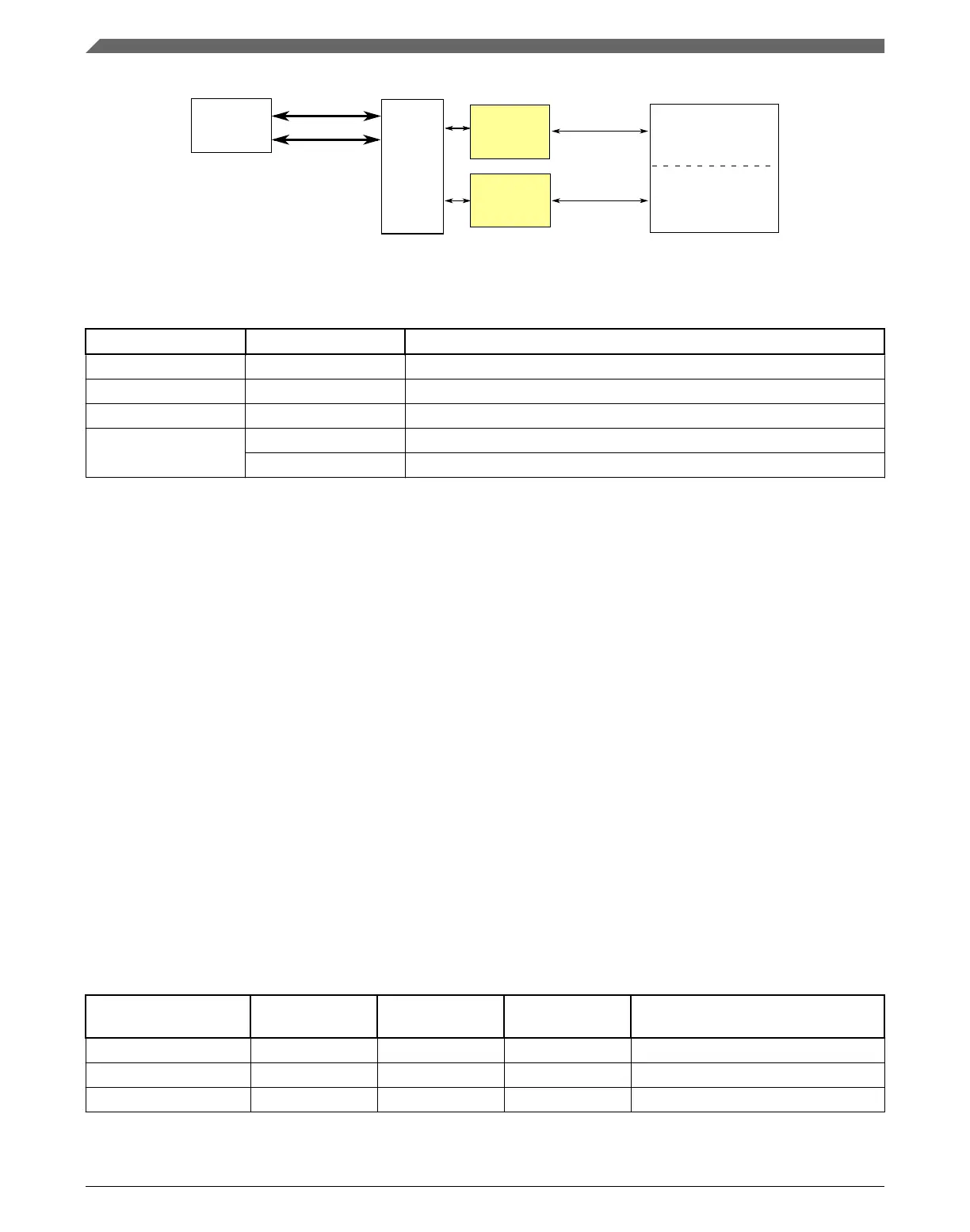
SRAM upper
Transfers
Cortex-M4
core
switch
SRAM lower
crossbar
SRAM
controller
SRAM
controller
Figure 3-22. SRAM configuration
Table 3-33. Reference links to related information
Topic Related module Reference
Full description SRAM SRAM
System memory map System memory map
Clocking Clock Distribution
Transfers SRAM controller SRAM controller
ARM Cortex-M4 core ARM Cortex-M4 core
3.5.3.1 SRAM sizes
This device contains SRAM accessed by bus masters through the cross-bar switch. The
on-chip SRAM is split into SRAM_L and SRAM_U regions where the SRAM_L and
SRAM_U ranges form a contiguous block in the memory map anchored at address
0x2000_0000. As such:
• SRAM_L is anchored to 0x1FFF_FFFF and occupies the space before this ending
address.
• SRAM_U is anchored to 0x2000_0000 and occupies the space after this beginning
address.
NOTE
Misaligned accesses across the 0x2000_0000 boundary are not
supported in the ARM Cortex-M4 architecture.
The amount of SRAM for the devices covered in this document is shown in the following
table.
Device SRAM_L size
(KB)
SRAM_U size
(KB)
Total SRAM (KB) Address Range
MK22FN512VDC12 64 64 128 0x1FFF_0000-0x2000_FFFF
MK22FN512VLL12 64 64 128 0x1FFF_0000-0x2000_FFFF
MK22FN512VLH12 64 64 128 0x1FFF_0000-0x2000_FFFF
Table continues on the next page...
Memories and memory interfaces
K22F Sub-Family Reference Manual, Rev. 4, 08/2016
88 NXP Semiconductors

 Loading...