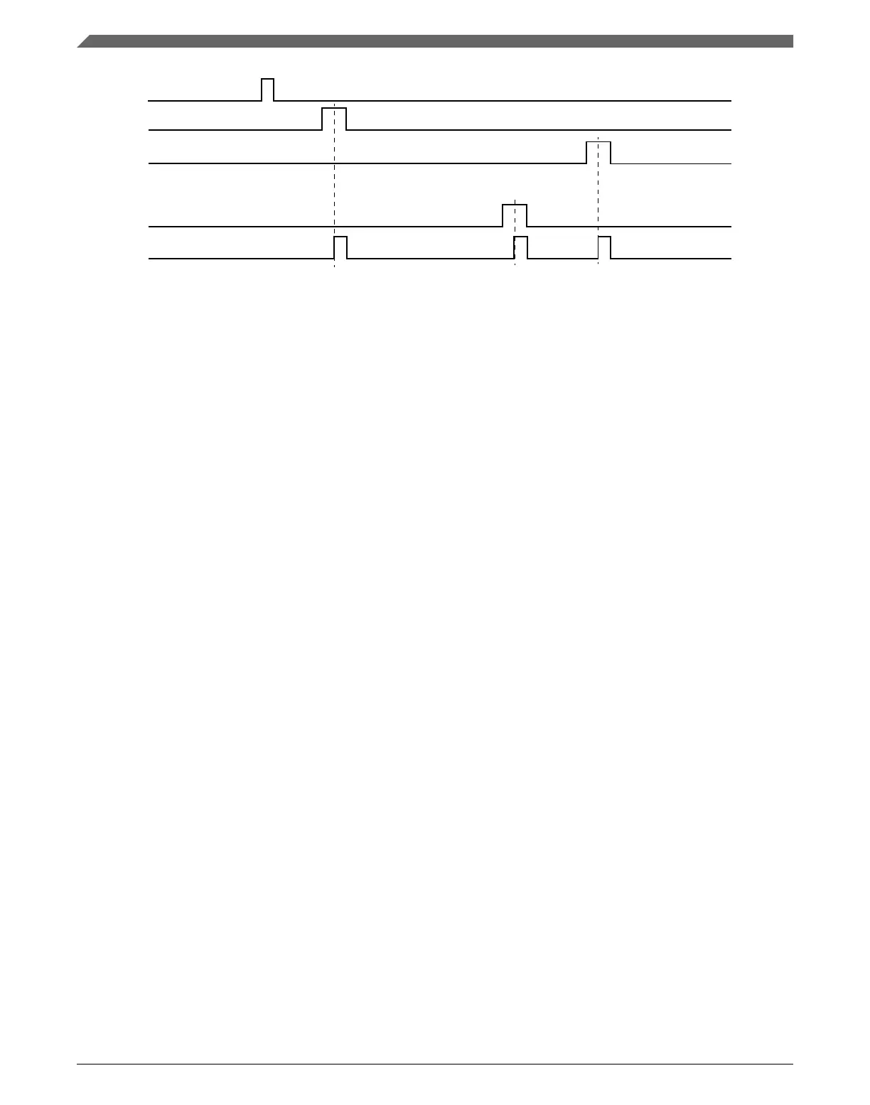
Trigger input event
Ch n pre-trigger 0
Ch n pre-trigger 1
Ch n pre-trigger M
Ch n trigger
... ... ... ...
Figure 38-2. Pre-trigger and trigger outputs
The delay in CHnDLYm register can be optionally bypassed, if CHnC1[TOS[m]] is
cleared. In this case, when the trigger input event occurs, the pre-trigger m is asserted
after 2 peripheral clock cycles.
The PDB can be configured for back-to-back operation. Back-to-back operation enables
the ADC conversion completions to trigger the next PDB channel pre-trigger and trigger
outputs, so that the ADC conversions can be triggered on the next set of configuration
and results registers. When back-to-back operation is enabled by setting CHnC1[BB[m]],
then the delay m is ignored and the pre-trigger m is asserted 2 peripheral cycles after the
acknowledgment m is received. The acknowledgment connections in this MCU are
described in Back-to-back acknowledgment connections.
When a pre-trigger from a PDB channel n is asserted, the associated lock of the pre-
trigger becomes active. The associated lock is released by the rising edge of the
corresponding ADCnSC1[COCO]; the ADCnSC1[COCO] should be cleared after the
conversion result is read, so that the next rising edge of ADCnSC1[COCO] can be
generated to clear the lock later. The lock becomes inactive when:
•
the rising edge of corresponding ADCnSC1[COCO] occurs,
• or the corresponding PDB pre-trigger is disabled,
• or the PDB is disabled
The channel n trigger output is suppressed when any of the locks of the pre-triggers in
channel n is active. If a new pre-trigger m asserts when there is active lock in the PDB
channel n, then a register flag bit CHnS[ERR[m]] (associated with the pre-trigger m) is
set. If SC[PDBEIE] is set, then the sequence error interrupt is generated. A sequence
error typically happens because the delay m is set too short and the pre-trigger m asserts
before the previously triggered ADC conversion finishes.
When the PDB counter reaches the value set in IDLY register, the SC[PDBIF] flag is set.
A PDB interrupt can be generated if SC[PDBIE] is set and SC[DMAEN] is cleared. If
SC[DMAEN] is set, then the PDB requests a DMA transfer when the SC[PDBIF] flag is
set.
Functional description
K22F Sub-Family Reference Manual, Rev. 4, 08/2016
884 NXP Semiconductors

 Loading...