•
DAC Interval x register (DACINTx)
•
PDB Pulse-Out y Delay register (POyDLY)
The internal registers of them are buffered and any values written to them are written first
to their buffers. The circumstances that cause their internal registers to be updated with
the values from the buffers are summarized as shown in the table below.
Table 38-2. Circumstances of update to the delay registers
SC[LDMOD] Update to the delay registers
00 The internal registers are loaded with the values from their buffers immediately after 1 is written to
SC[LDOK].
01 The PDB counter reaches the MOD register value after 1 is written to SC[LDOK].
10 A trigger input event is detected after 1 is written to SC[LDOK].
11 Either the PDB counter reaches the MOD register value, or a trigger input event is detected, after 1 is
written to SC[LDOK].
After 1 is written to SC[LDOK], the buffers cannot be written until the values in buffers
are loaded into their internal registers. SC[LDOK] is self-cleared when the internal
registers are loaded, so the application code can read it to determine the updates to the
internal registers.
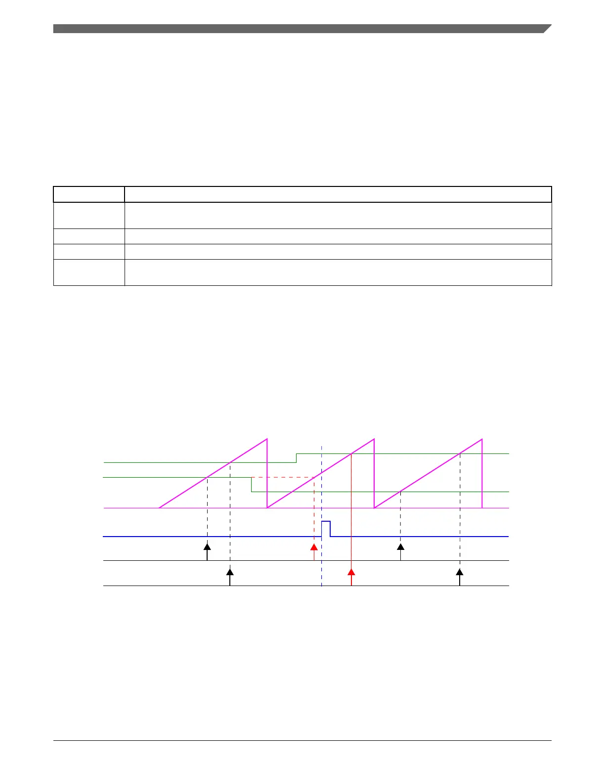
The following diagrams show the cases of the internal registers being updated with
SC[LDMOD] is 00 and x1.
PDB counter
Ch n pre-trigger 0
Ch n pre-trigger 1
CHnDLY1
CHnDLY0
SC[LDOK]
Figure 38-4. Registers update with SC[LDMOD] = 00
Chapter 38 Programmable Delay Block (PDB)
K22F Sub-Family Reference Manual, Rev. 4, 08/2016
NXP Semiconductors 887

 Loading...