UM10360 All information provided in this document is subject to legal disclaimers. © NXP B.V. 2013. All rights reserved.
User manual Rev. 3 — 19 December 2013 449 of 841
NXP Semiconductors
UM10360
Chapter 19: LPC176x/5x I2C0/1/2
19.8.11 Selecting the appropriate I
2
C data rate and duty cycle
Software must set values for the registers I2SCLH and I2SCLL to select the appropriate
data rate and duty cycle. I2SCLH defines the number of PCLK_I2C cycles for the SCL
HIGH time, I2SCLL defines the number of PCLK_I2C cycles for the SCL low time. The
frequency is determined by the following formula (PCLK_I2C is the frequency of the
peripheral bus APB):
(13)
The values for I2SCLL and I2SCLH must ensure that the data rate is in the appropriate
I
2
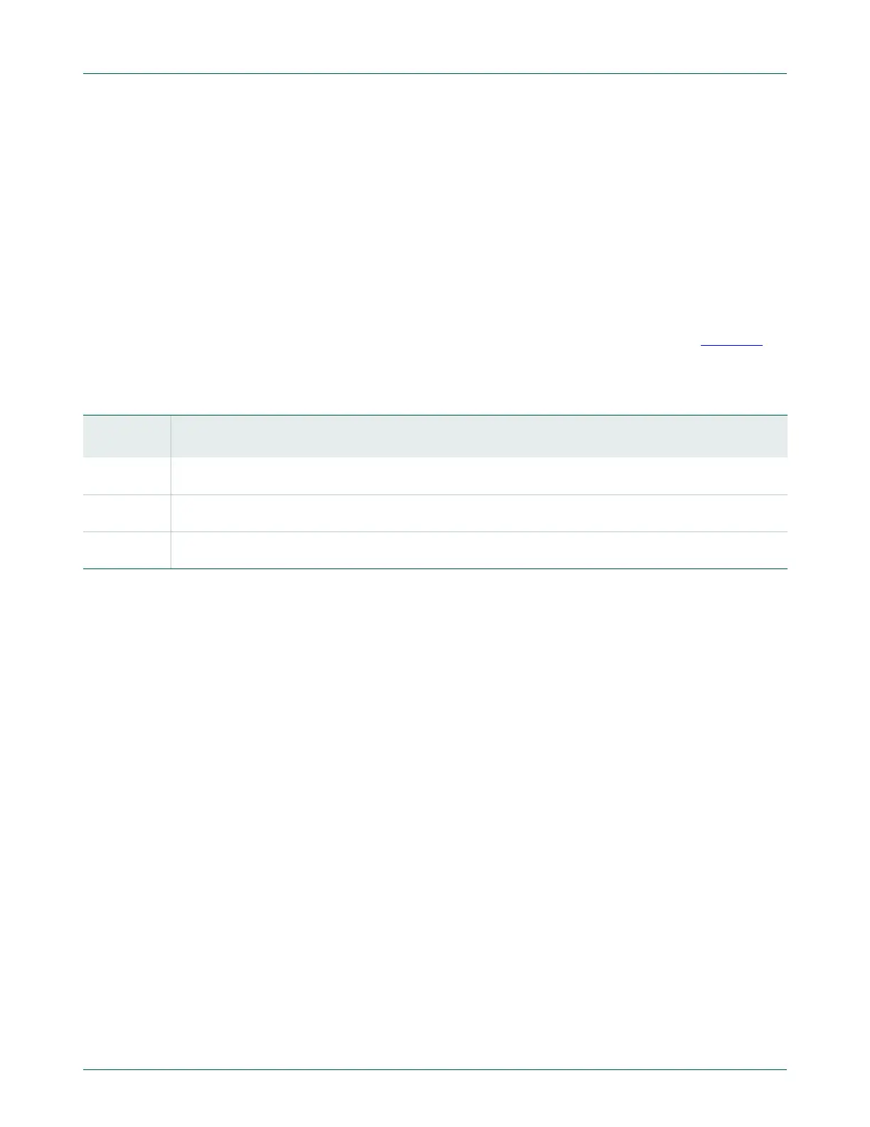
C data rate range. Each register value must be greater than or equal to 4. Table 394
gives some examples of I
2
C-bus rates based on PCLK_I2C frequency and I2SCLL and
I2SCLH values.
I2SCLL and I2SCLH values should not necessarily be the same. Software can set
different duty cycles on SCL by setting these two registers. For example, the I
2
C-bus
specification defines the SCL low time and high time at different values for a Fast Mode
and Fast Mode Plus I
2
C.
I
2
C
bitfrequency
PCLKI2C
I2CSCLH I2CSCLL+
---------------------------------------------------------
=
Table 394. Example I
2
C clock rates
I
2
C Rate
I2SCLL + I2SCLH values at PCLK_I2C (MHz)
6 8 10 12 16 20 30 40 50 60 70 80 90 100
100 kHz
(Standard)
60 80 100 120 160 200 300 400 500 600 700 800 900 1000
400 kHz
(Fast Mode)
15 20 25 30 40 50 75 100 125 150 175 200 225 250
1 MHz (Fast
Mode Plus)
- 8 10 12 16 20 30 40 50 60 70 80 90 100

 Loading...


