UM10360 All information provided in this document is subject to legal disclaimers. © NXP B.V. 2013. All rights reserved.
User manual Rev. 3 — 19 December 2013 9 of 841
NXP Semiconductors
UM10360
Chapter 1: LPC176x/5x Introductory information
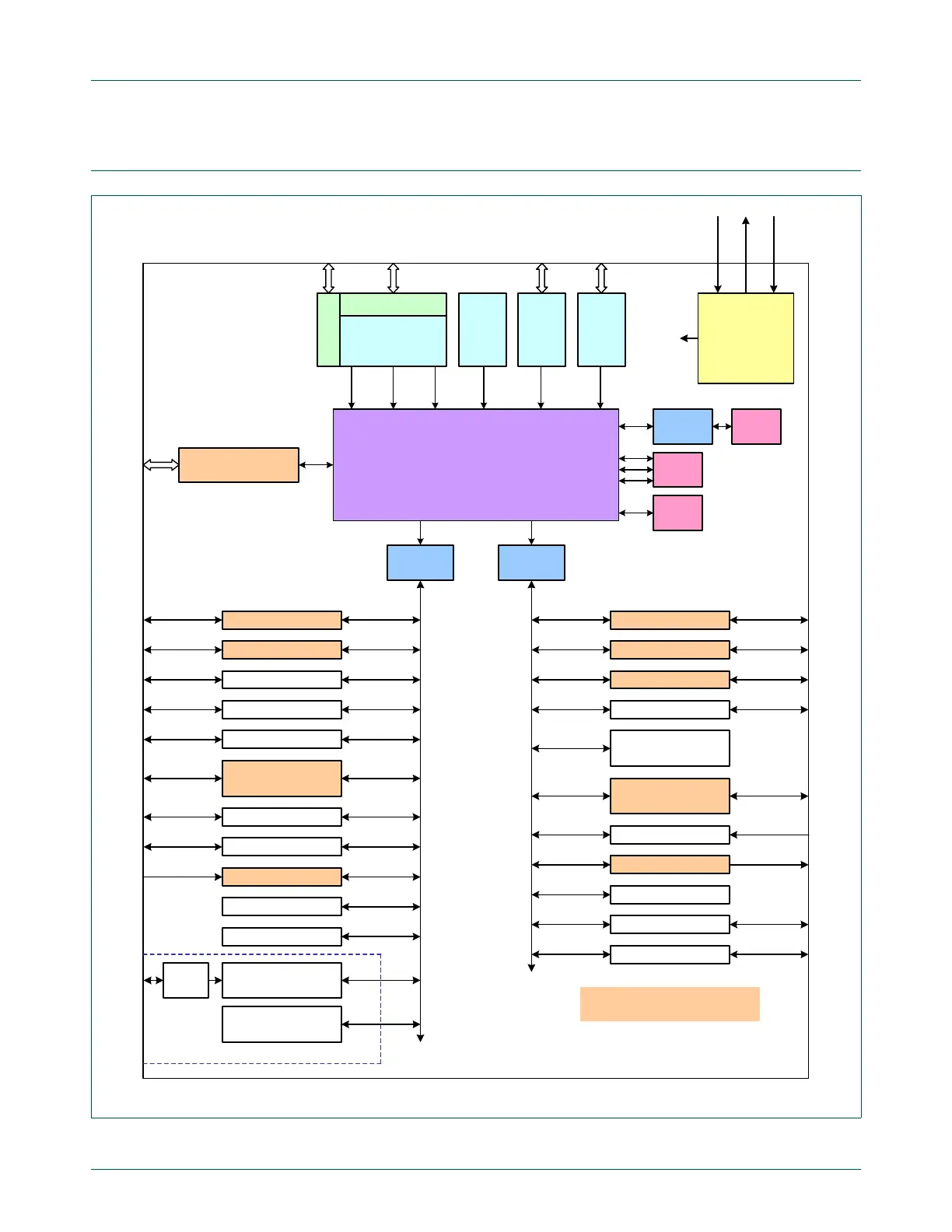
1.5 Simplified block diagram
Fig 1. LPC1768 simplified block diagram
AHB to
APB bridge
AHB to
APB bridge
APB slave group 1APB slave group 0
Note: shaded peripheral blocks
support General Purpose DMA
RTC Power Domain
Multilayer AHB Matrix
I
2
C2
I2S
UARTs 2 & 3
SSP0
Real Time Clock
20 bytes of backup
registers
SSP1
UARTs 0 & 1
CAN 1 & 2
I
2
C 0 & 1
SPI0
Capture/Compare
Timers 0 & 1
Watchdog Timer
PWM1
12-bit ADC
Pin Connect Block
GPIO Interrupt Ctl
32 kHz
oscillator
DMA
controller
Clock Generation,
Power Control,
Brownout Detect,
and other
system functions
RST
Xtalin
Xtalout
Clocks
and
Controls
Ethernet
PHY
interface
Ethernet
10/100
MAC
USB
device,
host,
OTG
USB
interface
JTAG
interface
ARM Cortex-M3
Test/Debug Interface
System
bus
D-code
bus
I-code
bus
ROM
8 kB
SRAM
64 kB
Trace
Port
Trace Module
High Speed GPIO
Capture/Compare
Timers 2 & 3
External Interrupts
DAC
System Control
Motor Control PWM
Quadrature Encoder
Repetitive Interrupt
Timer
Flash
512 kB
Flash
Accelerator

 Loading...


