UM10360 All information provided in this document is subject to legal disclaimers. © NXP B.V. 2013. All rights reserved.
User manual Rev. 3 — 19 December 2013 276 of 841
NXP Semiconductors
UM10360
Chapter 13: LPC176x/5x USB OTG
13.7 Pin configuration
The OTG controller has one USB port.
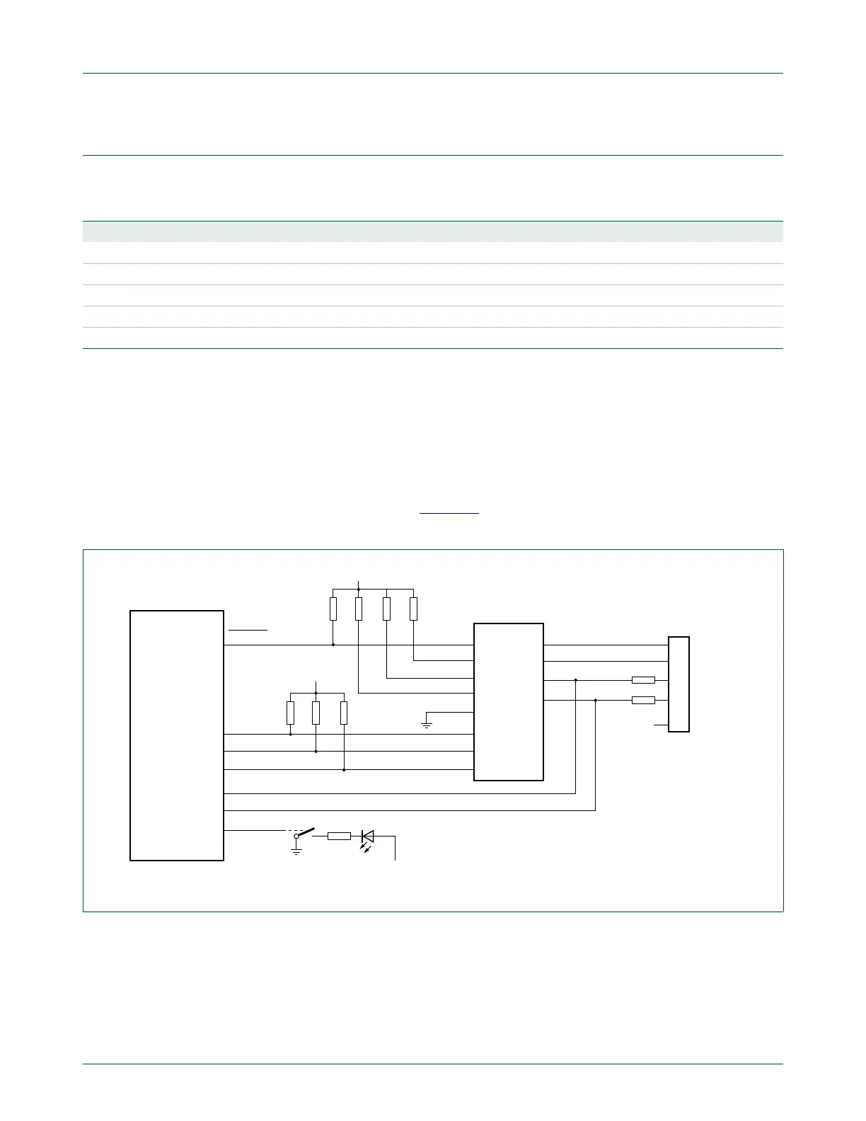
The following figures show different ways to realize connections to an USB device. The
example described here uses an ISP1302 (ST-Ericsson) for the external OTG transceiver
and the USB Host power switch LM3526-L (National Semiconductors).
13.7.1 Connecting the USB port to an external OTG transceiver
For OTG functionality an external OTG transceiver must be connected to the LPC176x/5x:
Use the internal USB transceiver for USB signalling and use the external OTG transceiver
for OTG functionality only (see Figure 35
). This option uses the internal transceiver in
VP/VM mode.
Table 255. USB OTG port pins
Pin name Direction Description Pin category
USB_D+ I/O Positive differential data USB Connector
USB_D
I/O Negative differential data USB Connector
USB_UP_LED O GoodLink LED control signal Control
USB_SCL I/O I
2
C serial clock External OTG transceiver
USB_SDA I/O I
2
C serial data External OTG transceiver
Fig 35. USB OTG port configuration
USB_D+
USB_D−
USB_SDA
USB_SCL
RSTOUT
LPC17xx
Mini-AB
connector
33 Ω
33 Ω
V
DD
V
DD
EINTn
RESET_N
ADR/PSW
SPEED
SUSPEND
OE_N/INT_N
SCL
SDA
INT_N
VBUS
ID
DP
DM
ISP1302
V
SSIO,
V
SSCORE
USB_UP_LED
V
DD

 Loading...


