UM10360 All information provided in this document is subject to legal disclaimers. © NXP B.V. 2013. All rights reserved.
User manual Rev. 3 — 19 December 2013 176 of 841
NXP Semiconductors
UM10360
Chapter 10: LPC176x/5x Ethernet
[1] The EMAC doesn't distinguish the frame type and frame length, so, e.g. when the IP(0x8000) or
ARP(0x0806) packets are received, it compares the frame type with the max length and gives the "Range"
error. In fact, this bit is not an error indication, but simply a statement by the chip regarding the status of the
received frame.
For multi-fragment frames, the value of the AlignmentError, RangeError, LengthError,
SymbolError and CRCError bits in all but the last fragment in the frame will be 0; likewise
the value of the FailFilter, Multicast, Broadcast, VLAN and ControlFrame bits is undefined.
The status of the last fragment in the frame will copy the value for these bits from the
MAC. All fragment statuses will have valid LastFrag, RxSize, Error, Overrun and
NoDescriptor bits.
10.15.2 Transmit descriptors and statuses
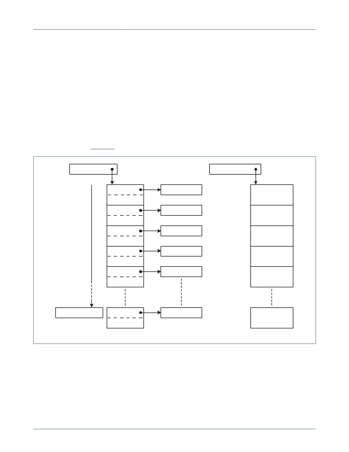
Figure 20 depicts the layout of the transmit descriptors in memory.
Transmit descriptors are stored in an array in memory. The lowest address of the transmit
descriptor array is stored in the TxDescriptor register, and must be aligned on a 4 byte
address boundary. The number of descriptors in the array is stored in the
TxDescriptorNumber register using a minus one encoding style i.e. if the array has 8
elements the register value should be 7. Parallel to the descriptors there is an array of
statuses. For each element of the descriptor array there is an associated status field in the
status array. The base address of the status array is stored in the TxStatus register, and
must be aligned on a 4 byte address boundary. During operation (when the transmit data
path is enabled) the TxDescriptor, TxStatus, and TxDescriptorNumber registers should
not be modified.
Fig 20. Transmit descriptor memory layout
1
2
3
4
5
StatusInfo
StatusInfo
StatusInfo
StatusInfo
StatusInfo
StatusInfo
PACKET
CONTROL
PACKET
CONTROL
PACKET
CONTROL
PACKET
CONTROL
PACKET
CONTROL
PACKET
CONTROL
TxStatus
TxDescriptorNumber
TxDescriptor
DATA BUFFER
DATA BUFFER
DATA BUFFER
DATA BUFFER
DATA BUFFER
DATA BUFFER

 Loading...


