UM10360 All information provided in this document is subject to legal disclaimers. © NXP B.V. 2013. All rights reserved.
User manual Rev. 3 — 19 December 2013 265 of 841
NXP Semiconductors
UM10360
Chapter 11: LPC176x/5x USB device controller
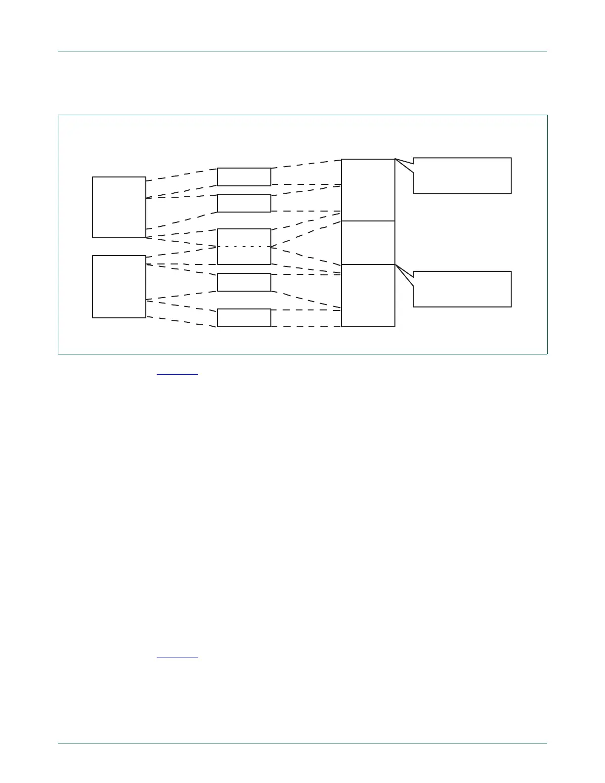
OUT transfers in ATLE mode
Figure 32 shows a typical OUT USB transfer in ATLE mode, where the host concatenates
two USB transfers of 160 bytes and 100 bytes, respectively. Given a MaxPacketSize of
64, the device hardware interprets this USB transfer as four packets of 64 bytes and a
short packet of 4 bytes. The third and fourth packets are concatenated. Note that in
Normal mode, the USB transfer would be interpreted as packets of 64, 64, 32, and 64 and
36 bytes.
It is now the responsibility of the DMA engine to separate these two USB transfers and put
them in the memory locations in the DMA_buffer_start_addr field of DMA Descriptor 1
(DD1) and DMA Descriptor 2 (DD2).
Hardware reads the two-byte-wide DMA_buffer_length at the offset (from the start of the
USB transfer) specified by Message_length_position from the incoming data packets and
writes it in the DMA_buffer_length field of the DD. To ensure that both bytes of the
DMA_buffer_length are extracted in the event they are split between two packets, the
flags LS_byte_extracted and MS_byte_extracted are set by hardware after the respective
byte is extracted. After the extraction of the MS byte, the DMA transfer continues as in the
normal mode.
The flags LS_byte_extracted and MS_byte_extracted are set to 0 by software when
preparing a new DD. Therefore, once a DD is retired, the transfer length is extracted again
for the next DD.
If DD1 is retired during the transfer of a concatenated packet (such as the third packet in
Figure 32
), and DD2 is not programmed (Next_DD_valid field of DD1 is 0), then DD1 is
retired with DD_status set to the DataOverrun status code. This is treated as an error
condition and the corresponding EPxx_DMA_ENABLE bit of USBEpDMASt is cleared by
hardware.
Fig 32. Data transfer in ATLE mode
DMA_buffer_start_addr
of DD1
DMA_buffer_start_addr
of DD2
data to be sent
by host driver
data in packets
as seen on USB
data to be stored in
RAM by DMA engine
160 bytes
100 bytes
64 bytes
64 bytes
32 bytes
32 bytes
64 bytes
4 bytes
160 bytes
100 bytes

 Loading...


