UM10360 All information provided in this document is subject to legal disclaimers. © NXP B.V. 2013. All rights reserved.
User manual Rev. 3 — 19 December 2013 306 of 841
NXP Semiconductors
UM10360
Chapter 14: LPC176x/5x UART0/2/3
immediately if the UARTn THR FIFO has held two or more characters at one time and
currently, the UnTHR is empty. The THRE interrupt is reset when a UnTHR write occurs or
a read of the UnIIR occurs and the THRE is the highest interrupt (UnIIR[3:1] = 001).
14.4.6 UARTn FIFO Control Register (U0FCR - 0x4000 C008, U2FCR -
0x4009 8008, U3FCR - 0x4009 C008)
The write-only UnFCR controls the operation of the UARTn Rx and TX FIFOs.
14.4.6.1 DMA Operation
The user can optionally operate the UART transmit and/or receive using DMA. The DMA
mode is determined by the DMA Mode Select bit in the FCR register. This bit only has an
affect when the FIFOs are enabled via the FIFO Enable bit in the FCR register.
UART receiver DMA
In DMA mode, the receiver DMA request is asserted on the event of the receiver FIFO
level becoming equal to or greater than trigger level, or if a character time-out occurs. See
the description of the RX Trigger Level above. The receiver DMA request is cleared by the
DMA controller.
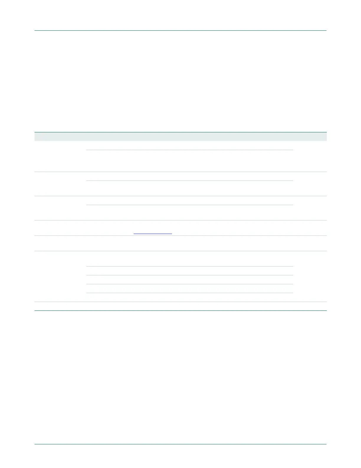
Table 278: UARTn FIFO Control Register (U0FCR - address 0x4000 C008, U2FCR - 0x4009 8008, U3FCR -
0x4007 C008) bit description
Bit Symbol Value Description Reset Value
0 FIFO Enable 0 UARTn FIFOs are disabled. Must not be used in the application. 0
1 Active high enable for both UARTn Rx and TX FIFOs and UnFCR[7:1] access.
This bit must be set for proper UART operation. Any transition on this bit will
automatically clear the related UART FIFOs.
1 RX FIFO
Reset
0 No impact on either of UARTn FIFOs. 0
1 Writing a logic 1 to UnFCR[1] will clear all bytes in UARTn Rx FIFO, reset the
pointer logic. This bit is self-clearing.
2TX FIFO
Reset
0 No impact on either of UARTn FIFOs. 0
1 Writing a logic 1 to UnFCR[2] will clear all bytes in UARTn TX FIFO, reset the
pointer logic. This bit is self-clearing.
3 DMA Mode
Select
When the FIFO enable bit (bit 0 of this register) is set, this bit selects the DMA
mode. See Section 14.4.6.1
.
0
5:4 - - Reserved, user software should not write ones to reserved bits. The value read
from a reserved bit is not defined.
NA
7:6 RX Trigger
Level
These two bits determine how many receiver UARTn FIFO characters must be
written before an interrupt or DMA request is activated.
0
00 Trigger level 0 (1 character or 0x01)
01 Trigger level 1 (4 characters or 0x04)
10 Trigger level 2 (8 characters or 0x08)
11 Trigger level 3 (14 characters or 0x0E)
31:8 - Reserved, user software should not write ones to reserved bits. NA

 Loading...


