UM10360 All information provided in this document is subject to legal disclaimers. © NXP B.V. 2013. All rights reserved.
User manual Rev. 3 — 19 December 2013 433 of 841
NXP Semiconductors
UM10360
Chapter 19: LPC176x/5x I2C0/1/2
19.6.2 Master Receiver mode
In the master receiver mode, data is received from a slave transmitter. The transfer is
initiated in the same way as in the master transmitter mode. When the START condition
has been transmitted, the interrupt service routine must load the slave address and the
data direction bit to the I
2
C Data register (I2DAT), and then clear the SI bit. In this case,
the data direction bit (R/W) should be 1 to indicate a read.
When the slave address and data direction bit have been transmitted and an
acknowledge bit has been received, the SI bit is set, and the Status Register will show the
status code. For master mode, the possible status codes are 0x40, 0x48, or 0x38. For
slave mode, the possible status codes are 0x68, 0x78, or 0xB0. For details, refer to
Table 399
.
When the LPC176x/5x needs to acknowledge a received byte, the AA bit needs to be set
accordingly prior to clearing the SI bit and initiating the byte read. When the LPC176x/5x
needs to not acknowledge a received byte, the AA bit needs to be cleared prior to clearing
the SI bit and initiating the byte read.
Note that the last received byte is always followed by a "Not Acknowledge" from the
LPC176x/5x so that the master can signal the slave that the reading sequence is finished
and that it needs to issue a STOP or repeated START Command. Once the "Not
Acknowledge has been sent and the SI bit is set, the LPC176x/5x can send either a STOP
(STO bit is set) or a repeated START (STA bit is set). Then the SI bit is cleared to initiate
the requested operation.
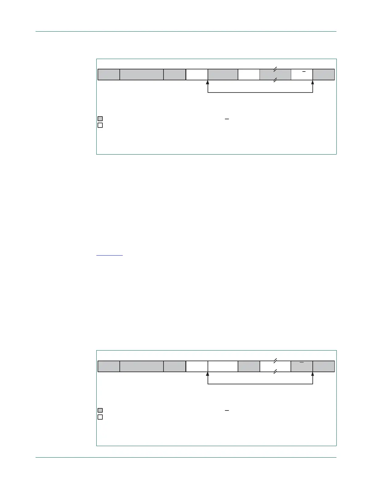
Fig 85. Format in the Master Transmitter mode
A = Acknowledge (SDA low)
A = Not acknowledge (SDA high)
S = START condition
P = STOP condition
S SLAVE ADDRESS RW=0 A DATA A
A/A
P
from Master to Slave
from Slave to Master
DATA
n bytes data transmitted
Fig 86. Format of Master Receiver mode
DATA
A = Acknowledge (SDA low)
A = Not acknowledge (SDA high)
S = START condition
P = STOP condition
S SLAVE ADDRESS RW=1 A DATA P
n bytes data received
from Master to Slave
from Slave to Master
A
A

 Loading...


