UM10360 All information provided in this document is subject to legal disclaimers. © NXP B.V. 2013. All rights reserved.
User manual Rev. 3 — 19 December 2013 50 of 841
NXP Semiconductors
UM10360
Chapter 4: LPC176x/5x Clocking and power control
PLL1 must be set up, enabled, and lock established before it may be used as a clock
source for the USB subsystem. The hardware does not insure that the PLL is locked
before it is connected nor does it automatically disconnect the PLL if lock is lost during
operation.
4.6.3 PLL1 Configuration register (PLL1CFG - 0x400F C0A4)
The PLL1CFG register contains the PLL1 multiplier and divider values. Changes to the
PLL1CFG register do not take effect until a correct PLL1 feed sequence has been given
(see Section 4.6.6
). Calculations for the PLL1 frequency, and multiplier and divider values
are found in Section 4.6.9
.
4.6.4 PLL1 Status register (PLL1STAT - 0x400F C0A8)
The read-only PLL1STAT register provides the actual PLL1 parameters that are in effect
at the time it is read, as well as the PLL1 status. PLL1STAT may disagree with values
found in PLL1CON and PLL1CFG because changes to those registers do not take effect
until a proper PLL1 feed has occurred (see Section 4.6.6 “
PLL1 Feed register (PLL1FEED
- 0x400F C0AC)”).
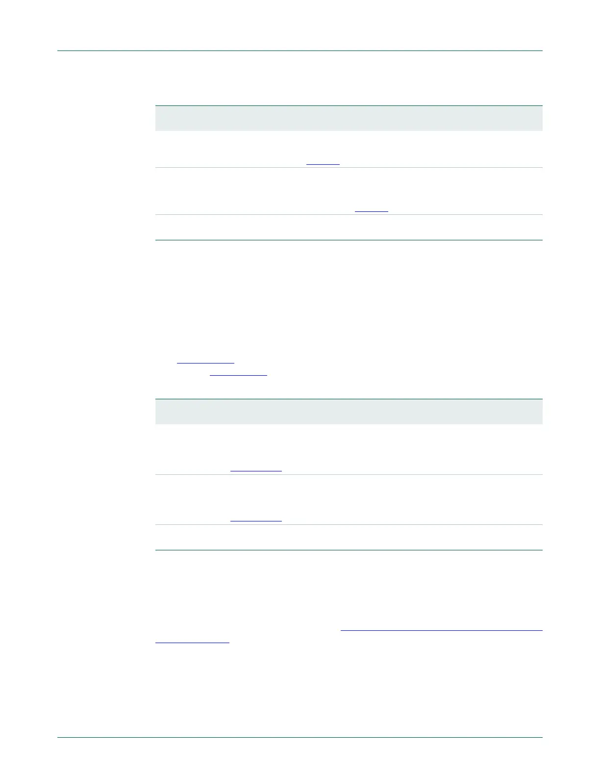
Table 30. PLL1 Control register (PLL1CON - address 0x400F C0A0) bit description
Bit Symbol Description Reset
value
0 PLLE1 PLL1 Enable. When one, and after a valid PLL1 feed, this bit will
activate PLL1 and allow it to lock to the requested frequency. See
PLL1STAT register, Table 32
.
0
1 PLLC1 PLL1 Connect. Setting PLLC to one after PLL1 has been enabled and
locked, then followed by a valid PLL1 feed sequence causes PLL1 to
become the clock source for the USB subsystem via the USB clock
divider. See PLL1STAT register, Table 32
.
0
31:2 - Reserved, user software should not write ones to reserved bits. The
value read from a reserved bit is not defined.
NA
Table 31. PLL Configuration register (PLL1CFG - address 0x400F C0A4) bit description
Bit Symbol Description Reset
value
4:0 MSEL1 PLL1 Multiplier value. Supplies the value "M" in the PLL1 frequency
calculations.
Note: For details on selecting the right value for MSEL1 see
Section 4.6.8
.
0
6:5 PSEL1 PLL1 Divider value. Supplies the value "P" in the PLL1 frequency
calculations.
Note: For details on selecting the right value for PSEL1 see
Section 4.6.8
.
0
31:7 - Reserved, user software should not write ones to reserved bits. The
value read from a reserved bit is not defined.
NA

 Loading...


