UM10360 All information provided in this document is subject to legal disclaimers. © NXP B.V. 2013. All rights reserved.
User manual Rev. 3 — 19 December 2013 477 of 841
NXP Semiconductors
UM10360
Chapter 20: LPC176x/5x I2S
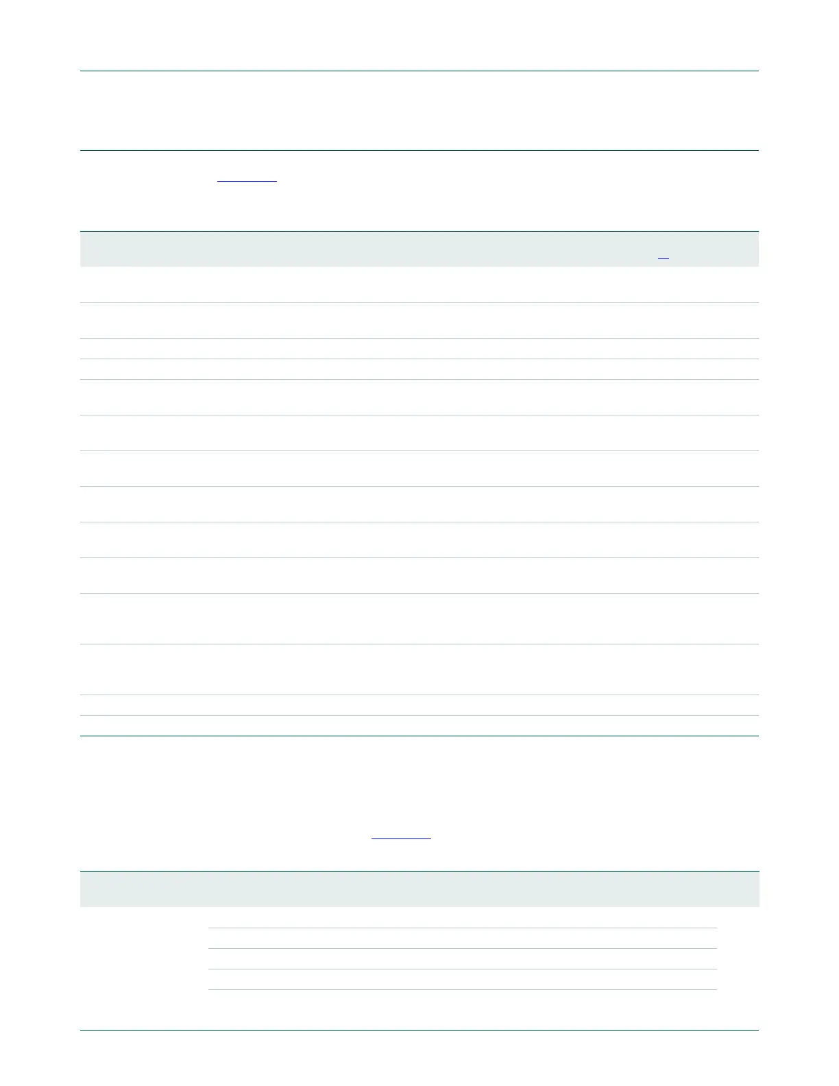
20.5 Register description
Table 404 shows the registers associated with the I
2
S interface and a summary of their
functions. Following the table are details for each register.
[1] Reset Value reflects the data stored in used bits only. It does not include reserved bits content.
20.5.1 Digital Audio Output register (I2SDAO - 0x400A 8000)
The I2SDAO register controls the operation of the I
2
S transmit channel. The function of
bits in DAO are shown in Table 405
.
Table 404. I
2
S register map
Name Description Access Reset
Value
[1]
Address
I2SDAO Digital Audio Output Register. Contains control bits for the I
2
S transmit
channel.
R/W 0x87E1 0x400A 8000
I2SDAI Digital Audio Input Register. Contains control bits for the I
2
S receive
channel.
R/W 0x07E1 0x400A 8004
I2STXFIFO Transmit FIFO. Access register for the 8
32-bit transmitter FIFO. WO 0 0x400A 8008
I2SRXFIFO Receive FIFO. Access register for the 8
32-bit receiver FIFO. RO 0 0x400A 800C
I2SSTATE Status Feedback Register. Contains status information about the I
2
S
interface.
RO 0x7 0x400A 8010
I2SDMA1 DMA Configuration Register 1. Contains control information for DMA
request 1.
R/W 0 0x400A 8014
I2SDMA2 DMA Configuration Register 2. Contains control information for DMA
request 2.
R/W 0 0x400A 8018
I2SIRQ Interrupt Request Control Register. Contains bits that control how the
I
2
S interrupt request is generated.
R/W 0 0x400A 801C
I2STXRATE Transmit MCLK divider. This register determines the I
2
S TX MCLK rate
by specifying the value to divide PCLK by in order to produce MCLK.
R/W 0 0x400A 8020
I2SRXRATE Receive MCLK divider. This register determines the I
2
S RX MCLK rate
by specifying the value to divide PCLK by in order to produce MCLK.
R/W 0 0x400A 8024
I2STXBITRATE Transmit bit rate divider. This register determines the I
2
S transmit bit
rate by specifying the value to divide TX_MCLK by in order to produce
the transmit bit clock.
R/W 0 0x400A 8028
I2SRXBITRATE Receive bit rate divider. This register determines the I
2
S receive bit rate
by specifying the value to divide RX_MCLK by in order to produce the
receive bit clock.
R/W 0 0x400A 802C
I2STXMODE Transmit mode control. R/W 0 0x400A 8030
I2SRXMODE Receive mode control. R/W 0 0x400A 8034
Table 405: Digital Audio Output register (I2SDAO - address 0x400A 8000) bit description
Bit Symbol Value Description Reset
Value
1:0 wordwidth Selects the number of bytes in data as follows: 01
00 8-bit data
01 16-bit data
10 Reserved, do not use this setting
11 32-bit data

 Loading...


