UM10360 All information provided in this document is subject to legal disclaimers. © NXP B.V. 2013. All rights reserved.
User manual Rev. 3 — 19 December 2013 287 of 841
NXP Semiconductors
UM10360
Chapter 13: LPC176x/5x USB OTG
I
2
C related interrupts are set in the I2C_STS register and routed, if enabled by I2C_CTL,
to the USB_I2C_INT bit.
For more details on the interrupts created by device controller, see the USB device
chapter. For interrupts created by the host controllers, see the OHCI specification.
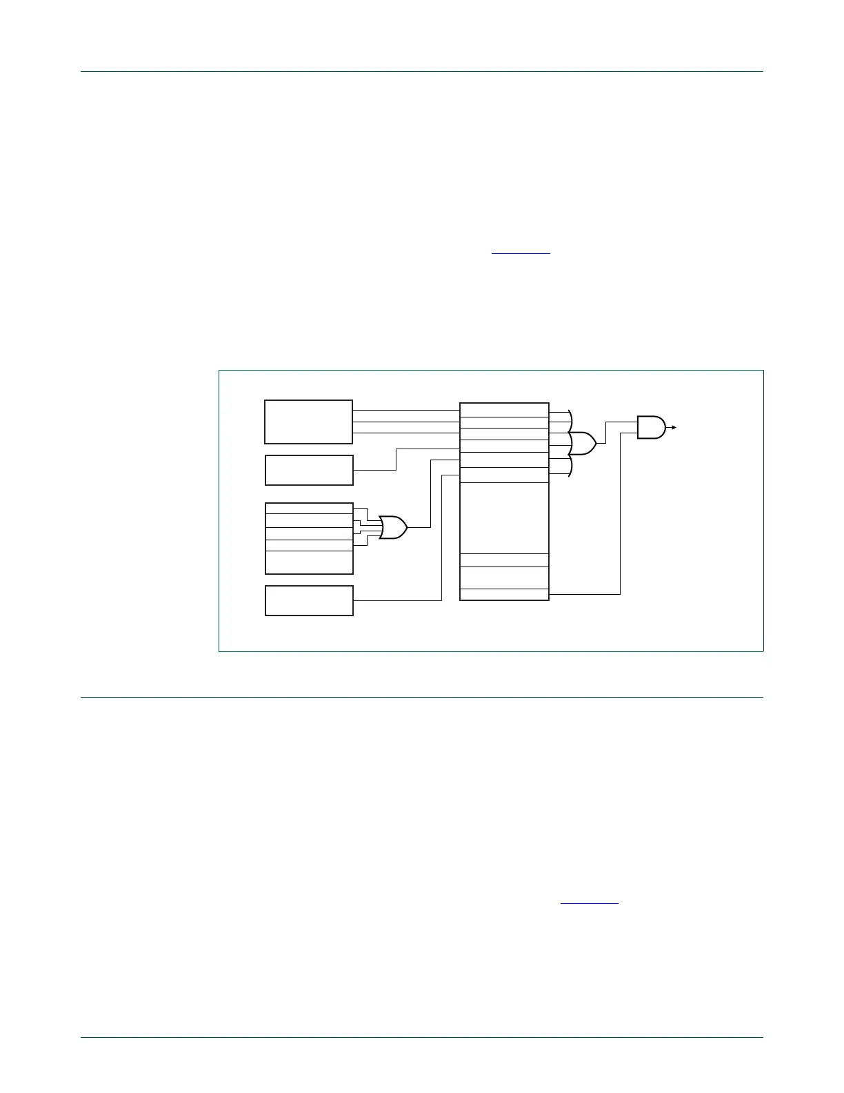
The EN_USB_INTS bit in the USBIntSt register enables the routing of any of the USB
related interrupts to the NVIC controller (see Figure 38
).
Remark: During the HNP switching between host and device with the OTG stack active,
an action may raise several levels of interrupts. It is advised to let the OTG stack initiate
any actions based on interrupts and ignore device and host level interrupts. This means
that during HNP switching, the OTG stack provides the communication to the host and
device controllers.
13.9 HNP support
This section describes the hardware support for the Host Negotiation Protocol (HNP)
provided by the OTG controller.
When two dual-role OTG devices are connected to each other, the plug inserted into the
mini-AB receptacle determines the default role of each device. The device with the mini-A
plug inserted becomes the default Host (A-device), and the device with the mini-B plug
inserted becomes the default Peripheral (B-device).
Once connected, the default Host (A-device) and the default Peripheral (B-device) can
switch Host and Peripheral roles using HNP.
The context of the OTG controller operation is shown in Figure 39
. Each controller (Host,
Device, or OTG) communicates with its software stack through a set of status and control
registers and interrupts. In addition, the OTG software stack communicates with the
external OTG transceiver through the I
2
C interface and the external transceiver interrupt
signal.
Fig 38. USB OTG interrupt handling
USB_INT_REQ_HP
USB_INT_REQ_LP
USB_INT_REQ_DMA
EN_USB_INTS
to NVIC
USB_HOST_INT
USB_OTG_INT
USB_I2C_INT
USB_NEED_CLOCK
USBIntSt
USB DEVICE
INTERRUPTS
USB HOST
INTERRUPTS
OTGIntSt
TMR
REMOVE_PU
HNP_SUCCESS
HNP_FAILURE
USB I2C
INTERRUPTS

 Loading...


