UM10360 All information provided in this document is subject to legal disclaimers. © NXP B.V. 2013. All rights reserved.
User manual Rev. 3 — 19 December 2013 431 of 841
NXP Semiconductors
UM10360
Chapter 19: LPC176x/5x I2C0/1/2
19.4.1 I
2
C FAST Mode Plus
Fast Mode Plus is a 1 Mbit/sec transfer rate to communicate with the I
2
C products which
the NXP Semiconductors is now providing.
In order to use Fast Mode Plus, the I
2
C0 pins must be configured, then rates above 400
kHz and up to 1 Mhz may be selected, see Table 394
. To configure the pins for Fast Mode
Plus, the SDADRV0 and SCLDRV0 bits in the I2CPADCFG register must be set, see
Section 8.5.21
.
19.5 Pin description
[1] I
2
C0 is only available in 100-pin LPC176x/5x devices. The SDA0 and SCL0 pins are open-drain pins to
comply with I
2
C specifications. The pins must be configured in the I2CPADCFG register for Fast Mode Plus.
The internal logic of the 3 I
2
C interfaces is identical. These interfaces can be brought out
to device pins in several ways, some of which have different pin I/O characteristics. I2C0
on pins P0[27] and P0[28] use specialized I
2
C pads that support fully spec compliant fast
mode, standard mode, and fast mode plus I
2
C.
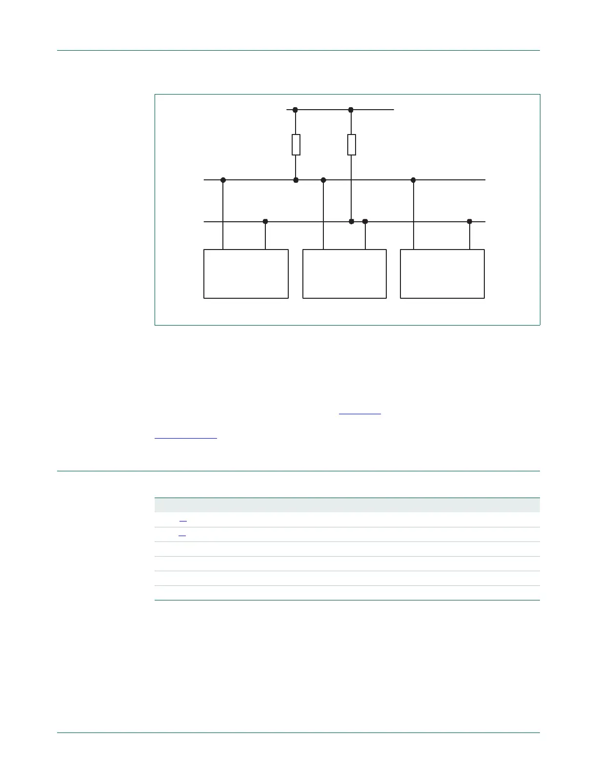
Fig 84. I
2
C-bus configuration
OTHER DEVICE WITH
I
2
C INTERFACE
pull-up
resistor
OTHER DEVICE WITH
I
2
C INTERFACE
LPCXXXX
SDA
SCL
I
2
C bus
SCL
SDA
pull-up
resistor
Table 380. I
2
C Pin Description
Pin Type Description
SDA0
[1]
Input/Output I
2
C0 Serial Data
SCL0
[1]
Input/Output I
2
C0 Serial Clock
SDA1 Input/Output I
2
C1 Serial Data
SCL1 Input/Output I
2
C1 Serial Clock
SDA2 Input/Output I
2
C2 Serial Data
SCL2 Input/Output I
2
C2 Serial Clock

 Loading...


