UM10360 All information provided in this document is subject to legal disclaimers. © NXP B.V. 2013. All rights reserved.
User manual Rev. 3 — 19 December 2013 329 of 841
NXP Semiconductors
UM10360
Chapter 15: LPC176x/5x UART1
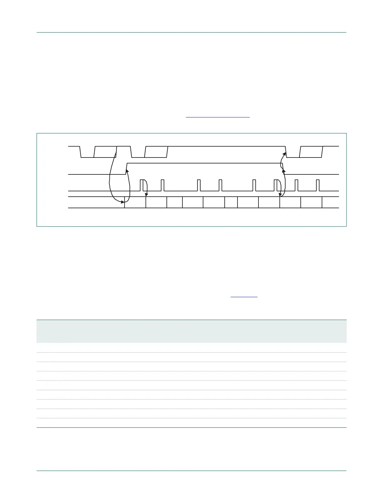
If Auto-RTS mode is disabled, the RTSen bit controls the RTS1 output of the UART1. If
Auto-RTS mode is enabled, hardware controls the RTS1 output, and the actual value of
RTS1 will be copied in the RTS Control bit of the UART1. As long as Auto-RTS is enabled,
the value of the RTS Control bit is read-only for software.
Example: Suppose the UART1 operating in ‘550 mode has trigger level in U1FCR set to
0x2 then if Auto-RTS is enabled the UART1 will de-assert the RTS1 output as soon as the
receive FIFO contains 8 bytes (Table 297 on page 326
). The RTS1 output will be
reasserted as soon as the receive FIFO hits the previous trigger level: 4 bytes.
15.4.9.2 Auto-CTS
The Auto-CTS function is enabled by setting the CTSen bit. If Auto-CTS is enabled the
transmitter circuitry in the U1TSR module checks CTS1 input before sending the next
data byte. When CTS1 is active (low), the transmitter sends the next byte. To stop the
transmitter from sending the following byte, CTS1 must be released before the middle of
the last stop bit that is currently being sent. In Auto-CTS mode a change of the CTS1
signal does not trigger a modem status interrupt unless the CTS Interrupt Enable bit is set,
Delta CTS bit in the U1MSR will be set though. Table 300
lists the conditions for
generating a Modem Status interrupt.
The auto-CTS function reduces interrupts to the host system. When flow control is
enabled, a CTS1 state change does not trigger host interrupts because the device
automatically controls its own transmitter. Without Auto-CTS, the transmitter sends any
Fig 48. Auto-RTS Functional Timing
start byte N stop start bits0..7 stop start bits0..7 stop
N-1 N N-1 N-1N-2 N-2 M+2 M+1 M M-1
UART1 Rx
RTS1 pin
UART1 Rx
FIFO level
UART1 Rx
FIFO read
~
~
~
~
~
~
~
~
~
~
Table 300: Modem status interrupt generation
Enable Modem Status
Interrupt (U1ER[3])
CTSen
(U1MCR[7])
CTS Interrupt
Enable (U1IER[7])
Delta CTS
(U1MSR[0])
Delta DCD or Trailing Edge RI
or Delta DSR (U1MSR[3] or
U1MSR[2] or U1MSR[1])
Modem Status
Interrupt
0xxxx No
10x00 No
10x1x Yes
10xx1 Yes
110x0 No
110x1 Yes
11100 No
1111x Yes
111x1 Yes

 Loading...


