UM10360 All information provided in this document is subject to legal disclaimers. © NXP B.V. 2013. All rights reserved.
User manual Rev. 3 — 19 December 2013 506 of 841
NXP Semiconductors
UM10360
Chapter 23: LPC176x/5x System Tick Timer
23.5 Register description
[1] Reset Value reflects the data stored in used bits only. It does not include content of reserved bits.
23.5.1 System Timer Control and status register (STCTRL - 0xE000 E010)
The STCTRL register contains control information for the System Tick Timer, and provides
a status flag.
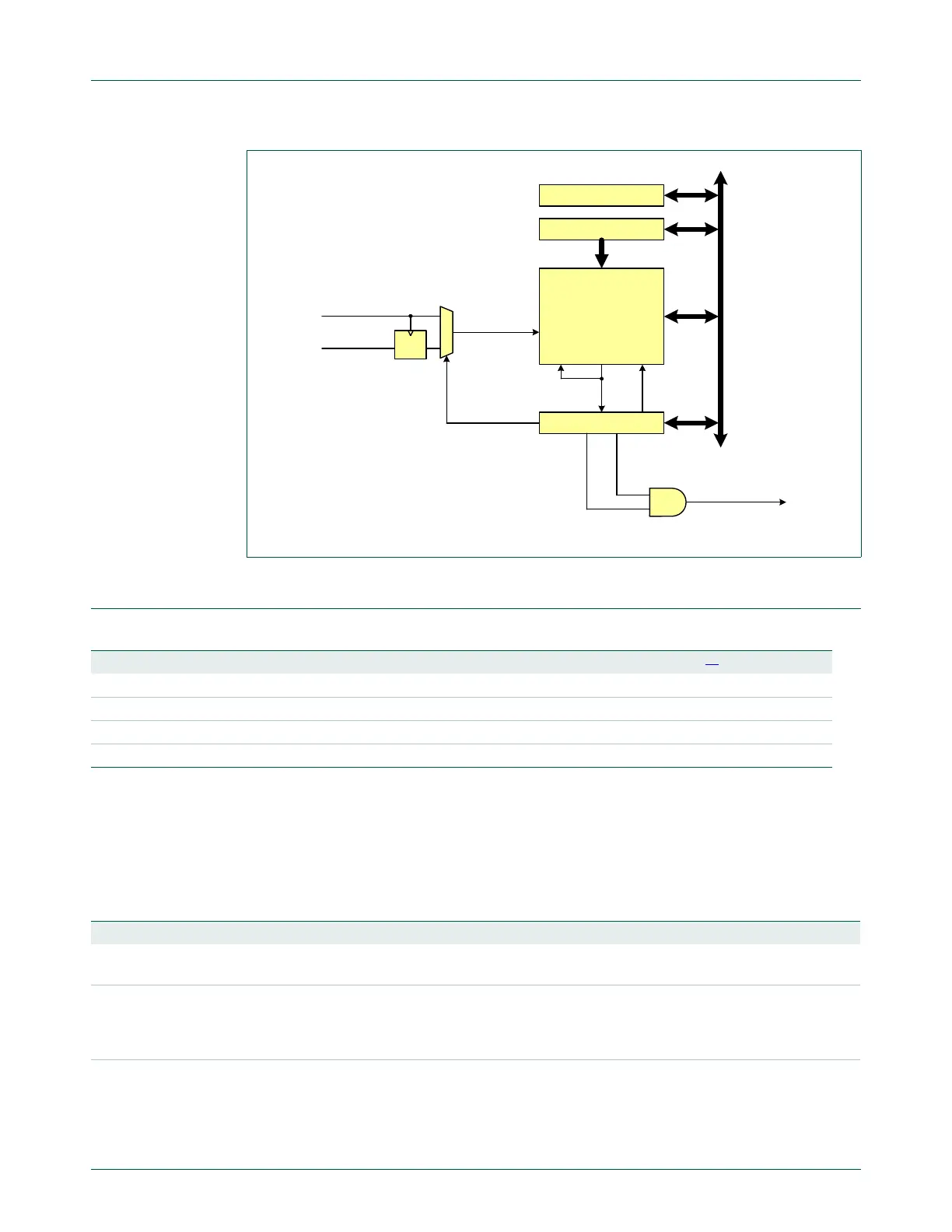
Fig 118. System Tick Timer block diagram
cclk
STCALIB
STRELOAD
STCURR
24-bit down counter
ENABLE
STCTRL
private
peripheral
bus
System Tick
interrupt
STCLK pin
CLKSOURCE
TICKINTCOUNTFLAG
load
under-
flow
count
enable
clock
DQ
load data
Table 438. System Tick Timer register map
Name Description Access Reset value
[1]
Address
STCTRL System Timer Control and status register R/W 0x4 0xE000 E010
STRELOAD System Timer Reload value register R/W 0 0xE000 E014
STCURR System Timer Current value register R/W 0 0xE000 E018
STCALIB System Timer Calibration value register R/W 0x000F 423F 0xE000 E01C
Table 439. System Timer Control and status register (STCTRL - 0xE000 E010) bit description
Bit Symbol Description Reset value
0 ENABLE System Tick counter enable. When 1, the counter is enabled. When 0,
the counter is disabled.
0
1 TICKINT System Tick interrupt enable. When 1, the System Tick interrupt is
enabled. When 0, the System Tick interrupt is disabled. When enabled,
the interrupt is generated when the System Tick counter counts down to
0.
0
2 CLKSOURCE System Tick clock source selection. When 1, the CPU clock is selected.
When 0, the external clock pin (STCLK) is selected.
1

 Loading...


