UM10360 All information provided in this document is subject to legal disclaimers. © NXP B.V. 2013. All rights reserved.
User manual Rev. 3 — 19 December 2013 542 of 841
NXP Semiconductors
UM10360
Chapter 25: LPC176x/5x Motor control PWM
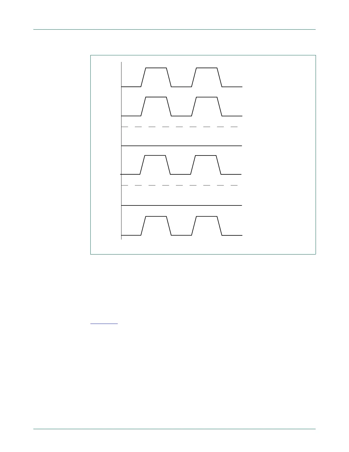
25.8.7 Three phase AC mode
The three-phase AC-mode is selected by setting the ACMODE bit in the MCCON register.
In this mode, the value of channel 0’s TC is routed to all channels for comparison with
their MAT registers. (The LIM1-2 registers are not used.)
Each channel controls its MCO output by comparing its MAT value to TC0.
Figure 127
shows sample waveforms for the six MCO outputs in three-phase AC mode.
The POLA bits are set to 0 for all three channels, so that for all MCO outputs the active
levels are high and the passive levels are low. Each channel has a different MAT value
which is compared to the MCTC0 value. In this mode the period value is identical for all
three channels and is determined by MCLIM0. The dead-time mode is disabled.
Fig 126. Three-phase DC mode sample waveforms
POLA0 = 0, INVBDC = 0
MCOA2
MCOB1
MCOA1
MCOB0
MCOA0
MCOB2
CCPB1 = 0, off-state
CCPB0 = 0, off-state
CCPA0 = 1, on-state
CCPA2 = 1, on-state
CCPA1 = 1, on-state
CCPB2 = 1, on-state

 Loading...


