UM10360 All information provided in this document is subject to legal disclaimers. © NXP B.V. 2013. All rights reserved.
User manual Rev. 3 — 19 December 2013 560 of 841
NXP Semiconductors
UM10360
Chapter 27: LPC176x/5x Real-Time Clock (RTC) and backup registers
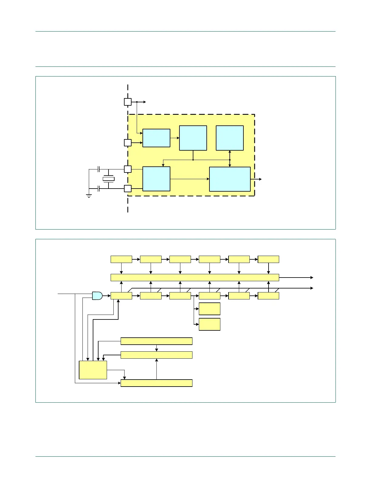
27.4 Architecture
Fig 130. RTC domain conceptual diagram
V
BAT
pin
Ultra-low
power
regulator
Power
selector
V
DD(REG)(3v3)
pin
Ultra-low
power
oscillator
to main regulator
1 Hz clock
RTC power
Backup
Registers
Real Time Clock
Functional Block
RTC power domain
RTCX1
RTCX2
RTC Alarm
& Interrupt
Fig 131. RTC functional block diagram
day of
year
second minute hour day month year
alarm compare
second minute hour day month year
day of
week
calibration counter
calibration compare register
calibration
control
logic
calibration compare
sign
bit
match
counter
reset
LSB
set
LSB
out
Time Registers
Alarm Registers
Calibration
Alarm out
and Alarm
Interrupts
Counter
Increment
Interrupts
1 Hz
Clock

 Loading...


