UM10360 All information provided in this document is subject to legal disclaimers. © NXP B.V. 2013. All rights reserved.
User manual Rev. 3 — 19 December 2013 539 of 841
NXP Semiconductors
UM10360
Chapter 25: LPC176x/5x Motor control PWM
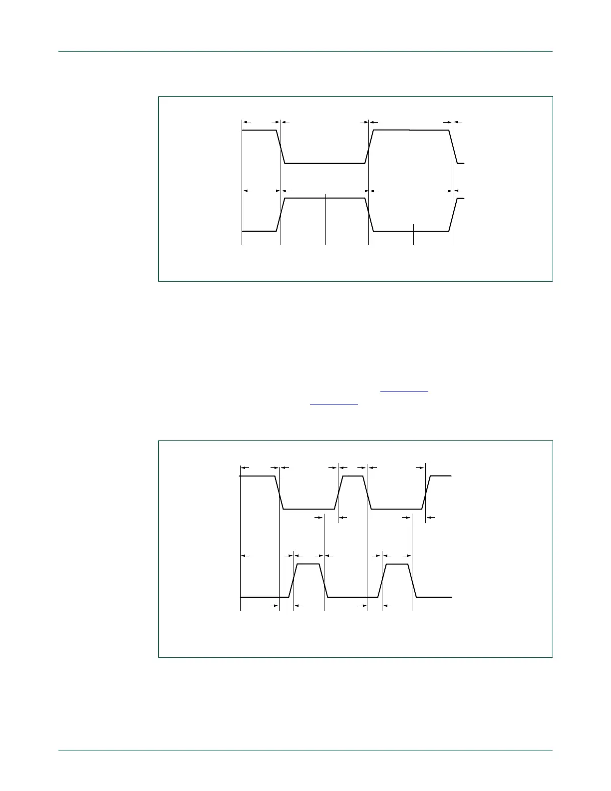
Dead-time counter
When the a channel’s DTE bit is set in MCCON, the dead-time counter delays the
passive-to-active transitions of both MCO outputs. The dead-time counter starts counting
down, from the channel’s DT value (in the MCDT register) to 0, whenever the channel’s A
or B output changes from active to passive. The transition of the other output from passive
to active is delayed until the dead-time counter reaches 0. During the dead time, the
MCOA and MCOB output levels are both passive. Figure 124
shows operation in edge
aligned mode with dead time, and Figure 125
shows center-aligned operation with dead
time.
Fig 123. Center-aligned PWM waveform without dead time, POLA = 0
Fig 124. Edge-aligned PWM waveform with dead time, POLA = 0
MAT MAT LIMLIM
0
0
POLA = 0
MCOA
MCOB
active
active
passive
passive
passive passiveactive
active
MAT MATLIM LIM
0
POLA = 0
timer reset timer reset
MCOA
MCOB
active active
passive
passive
passive
passive
active
active
DT
DT DT
DT

 Loading...


