UM10360 All information provided in this document is subject to legal disclaimers. © NXP B.V. 2013. All rights reserved.
User manual Rev. 3 — 19 December 2013 543 of 841
NXP Semiconductors
UM10360
Chapter 25: LPC176x/5x Motor control PWM
25.8.8 Interrupts
The MCPWM includes 10 possible interrupt sources:
• When any channel’s TC matches its Match register.
• When any channel’s TC matches its Limit register.
• When any channel captures the value of its TC into its Capture register, because a
selected edge occurs on any of MCI0-2.
• When all three channels’ outputs are forced to “A passive” state because the
MCABORT
pin goes low.
Section 25.7.3 “
MCPWM Interrupt registers” explains how to enable these interrupts, and
Section 25.7.2 “
MCPWM Capture Control register” describes how to map edges on the
MCI0-2 inputs to “capture events” on the three channels.
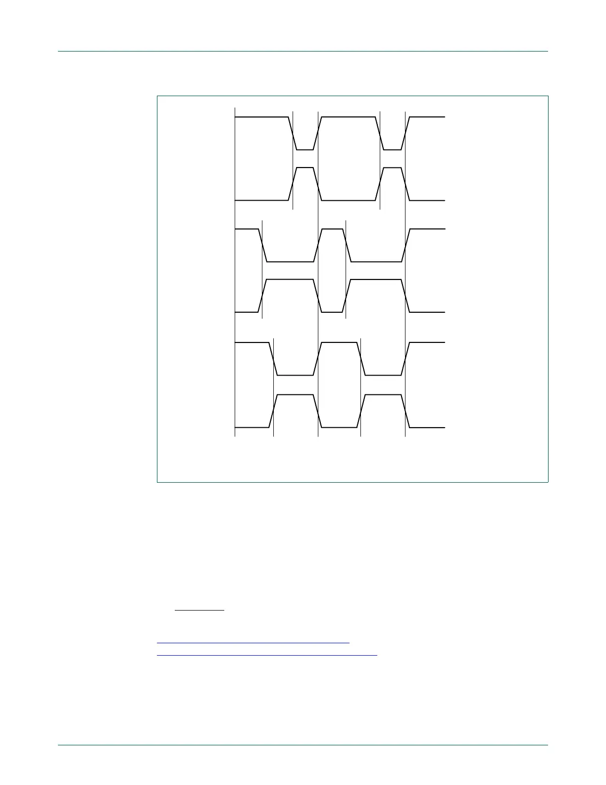
Fig 127. Three-phase AC mode sample waveforms, edge aligned PWM mode
POLA0 = 0
POLA2 = 0
POLA1 = 0
MCOA2
MCOB1
MCOA1
MCOB0
MCOA0
MCOB2
MAT0
MAT1
MAT1
MAT2
MAT2
LIM0 LIM0
0
timer reset timer reset

 Loading...


