UM10360 All information provided in this document is subject to legal disclaimers. © NXP B.V. 2013. All rights reserved.
User manual Rev. 3 — 19 December 2013 513 of 841
NXP Semiconductors
UM10360
Chapter 24: LPC176x/5x Pulse Width Modulator (PWM)
24.4 Sample waveform with rules for single and double edge control
A sample of how PWM values relate to waveform outputs is shown in Figure 120. PWM
output logic is shown in Figure 119
that allows selection of either single or double edge
controlled PWM outputs via the muxes controlled by the PWMSELn bits. The match
register selections for various PWM outputs is shown in Table 443
. This implementation
supports up to N-1 single edge PWM outputs or (N-1)/2 double edge PWM outputs, where
N is the number of match registers that are implemented. PWM types can be mixed if
desired.
[1] Identical to single edge mode in this case since Match 0 is the neighboring match register. Essentially,
PWM1 cannot be a double edged output.
[2] It is generally not advantageous to use PWM channels 3 and 5 for double edge PWM outputs because it
would reduce the number of double edge PWM outputs that are possible. Using PWM 2, PWM4, and
PWM6 for double edge PWM outputs provides the most pairings.
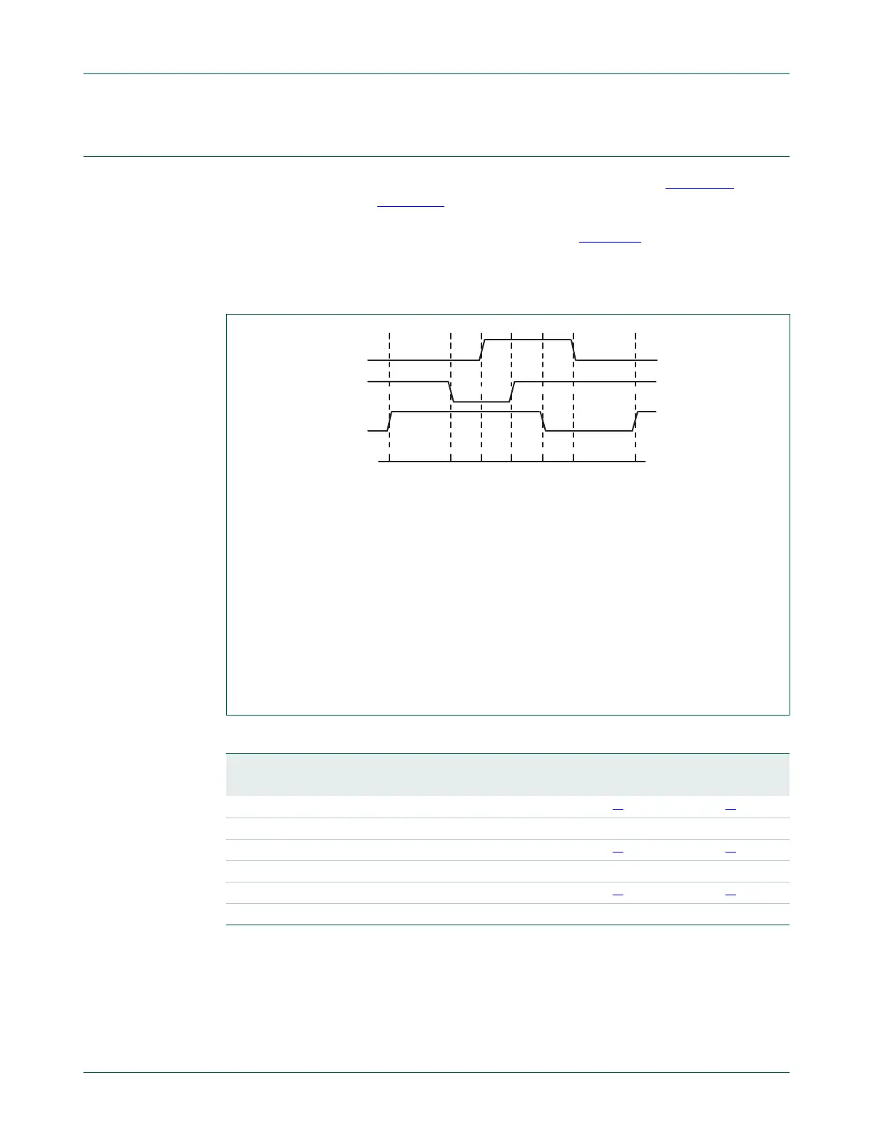
The waveforms show one PWM cycle and demonstrate PWM outputs under the following
conditions:
The timer is configured for PWM mode (counter resets to 1).
Match 0 is configured to reset the timer/counter when a match event occurs.
Control bits PWMSEL2 and PWMSEL4 are set.
The Match register values are as follows:
MR0 = 100 (PWM rate)
MR1 = 41, MR2 = 78 (PWM2 output)
MR3 = 53, MR4 = 27 (PWM4 output)
MR5 = 65 (PWM5 output)
Fig 120. Sample PWM waveforms
Table 443. Set and reset inputs for PWM Flip-Flops
PWM Channel Single Edge PWM (PWMSELn = 0) Double Edge PWM (PWMSELn = 1)
Set by Reset by Set by Reset by
1 Match 0 Match 1 Match 0
[1]
Match 1
[1]
2 Match 0 Match 2 Match 1 Match 2
3 Match 0 Match 3 Match 2
[2]
Match 3
[2]
4 Match 0 Match 4 Match 3 Match 4
5 Match 0 Match 5 Match 4
[2]
Match 5
[2]
6 Match 0 Match 6 Match 5 Match 6
PWM2
PWM4
PWM5
100
(counter is reset)
1 2741536578

 Loading...


