UM10360 All information provided in this document is subject to legal disclaimers. © NXP B.V. 2013. All rights reserved.
User manual Rev. 3 — 19 December 2013 465 of 841
NXP Semiconductors
UM10360
Chapter 19: LPC176x/5x I2C0/1/2
The I
2
C hardware only reacts to a bus error when it is involved in a serial transfer either as
a master or an addressed slave. When a bus error is detected, the I
2
C block immediately
switches to the not addressed slave mode, releases the SDA and SCL lines, sets the
interrupt flag, and loads the status register with 0x00. This status code may be used to
vector to a state service routine which either attempts the aborted serial transfer again or
simply recovers from the error condition as shown in Table 402
.
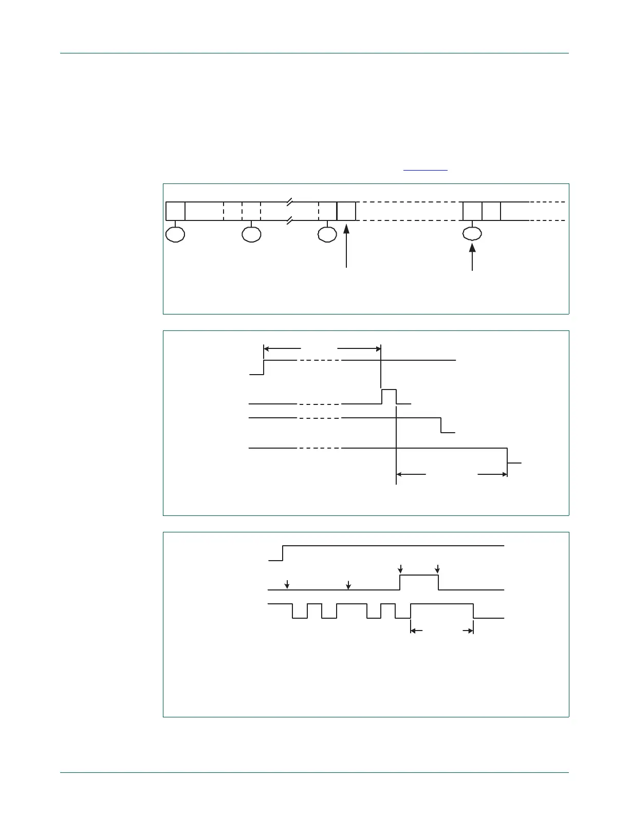
Fig 97. Simultaneous repeated START conditions from two masters
Fig 98. Forced access to a busy I
2
C-bus
(1) Unsuccessful attempt to send a START condition.
(2) SDA line is released.
(3) Successful attempt to send a START condition. State 08H is entered.
Fig 99. Recovering from a bus obstruction caused by a LOW level on SDA
SLAAWSLAS
18H
08H
ADATA
28H08H
OTHER MASTER
CONTINUES
other Master sends
repeated START earlier
S
retry
S P
SDA line
SCL line
STA flag
STO flag
time limit
start
condition
SDA line
SCL line
(1)
(2)
(1)
(3)
STA flag
start
condition

 Loading...


