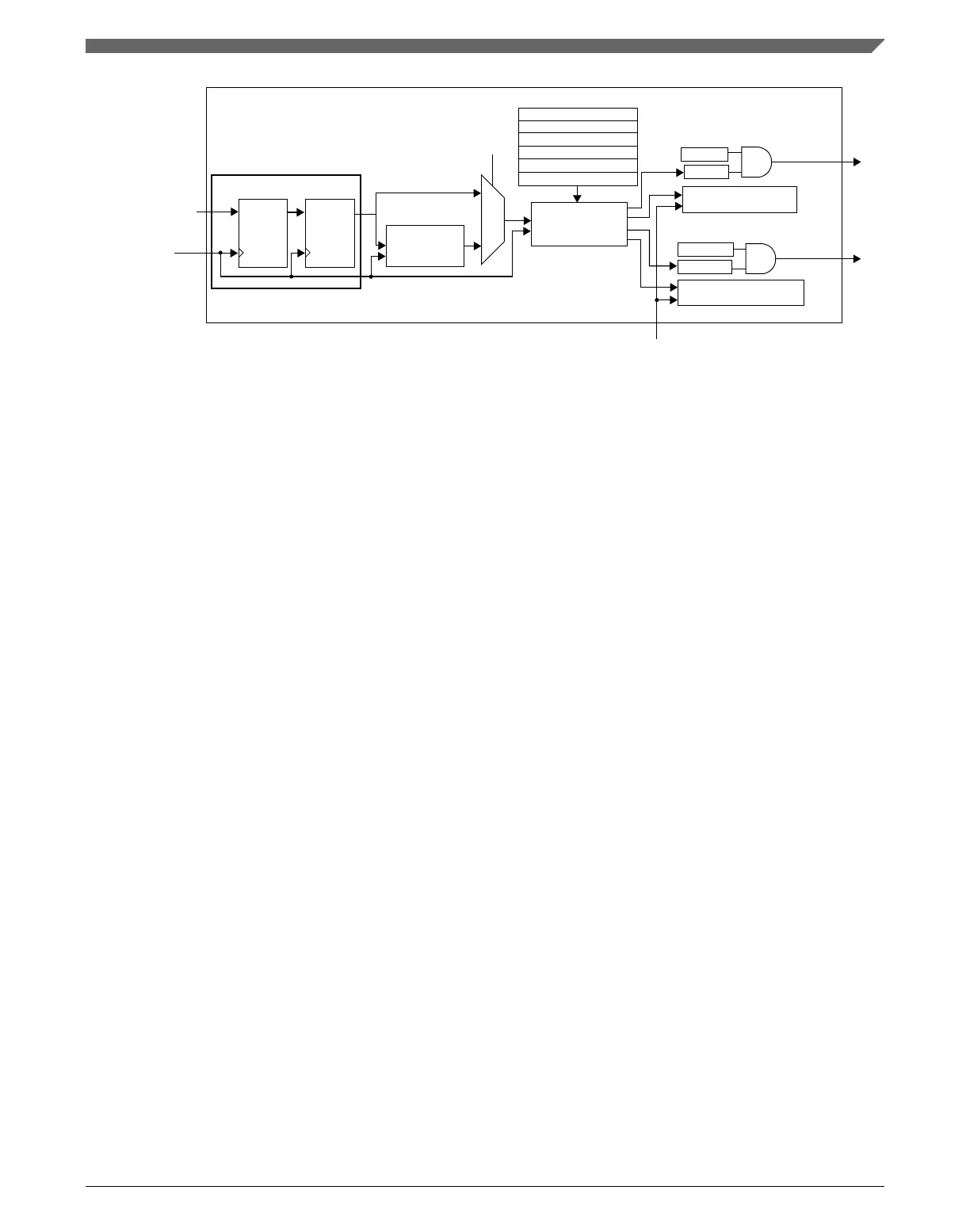
channel (n) input
system clock
synchronizer
Filter*
Dual edge capture
mode logic
is filter
enabled?
FTM counter
* Filtering function for dual edge capture mode is only available in the channels 0 and 2
channel (n)
interrupt
channel (n+1)
interrupt
C(n+1)V[15:0]
C(n)V[15:0]
CH(n+1)IE
CH(n+1)F
CH(n)IE
CH(n)F
FTMEN
DECAPEN
DECAP
MS(n)A
ELS(n)B:ELS(n)A
ELS(n+1)B:ELS(n+1)A
CLK CLK
D
Q
D
Q
0
1
Figure 39-83. Dual Edge Capture mode block diagram
The MS(n)A bit defines if the Dual Edge Capture mode is one-shot or continuous.
The ELS(n)B:ELS(n)A bits select the edge that is captured by channel (n), and ELS(n
+1)B:ELS(n+1)A bits select the edge that is captured by channel (n+1). If both
ELS(n)B:ELS(n)A and ELS(n+1)B:ELS(n+1)A bits select the same edge, then it is the
period measurement. If these bits select different edges, then it is a pulse width
measurement.
In the Dual Edge Capture mode, only channel (n) input is used and channel (n+1) input is
ignored.
If the selected edge by channel (n) bits is detected at channel (n) input, then CH(n)F bit is
set and the channel (n) interrupt is generated (if CH(n)IE = 1). If the selected edge by
channel (n+1) bits is detected at channel (n) input and (CH(n)F = 1), then CH(n+1)F bit is
set and the channel (n+1) interrupt is generated (if CH(n+1)IE = 1).
The C(n)V register stores the value of FTM counter when the selected edge by channel
(n) is detected at channel (n) input. The C(n+1)V register stores the value of FTM
counter when the selected edge by channel (n+1) is detected at channel (n) input.
In this mode, a coherency mechanism ensures coherent data when the C(n)V and C(n
+1)V registers are read. The only requirement is that C(n)V must be read before C(n
+1)V.
Note
• The CH(n)F, CH(n)IE, MS(n)A, ELS(n)B, and ELS(n)A
bits are channel (n) bits.
Chapter 39 FlexTimer Module (FTM)
K22F Sub-Family Reference Manual, Rev. 4, 08/2016
NXP Semiconductors 1007

 Loading...