AD5 [00101]
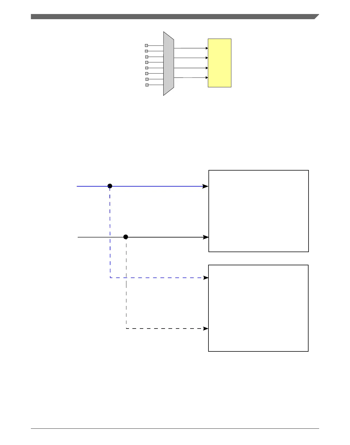
ADCx_SE4a
ADCx_SE5a
ADCx_SE6a
ADCx_SE7a
ADCx_SE4b
ADCx_SE5b
ADCx_SE6b
ADCx_SE7b
AD4 [00100]
AD6 [00110]
AD7 [00111]
ADC
Figure 3-31. ADCx_SEn channels a and b selection
3.7.1.5 ADC Hardware Interleaved Channels
The AD8 and AD9 channels on ADCx are interleaved in hardware using the following
configuration.
ADC0
AD8
AD9
ADC1
AD8
AD9
ADC0_SE8
/ADC1_SE8
ADC0_SE9
/ADC1_SE9
Figure 3-32. ADC hardware interleaved channels integration
There are other pins on this device that have a similar interleave configuration, including
the plus side of differential pair pins available (for example ADC0_DP0 and
ADC1_DP3). Refer to the Signal Multiplexing and Pin Assignments table for this device.
Chapter 3 Chip Configuration
K22F Sub-Family Reference Manual, Rev. 4, 08/2016
NXP Semiconductors 101

 Loading...