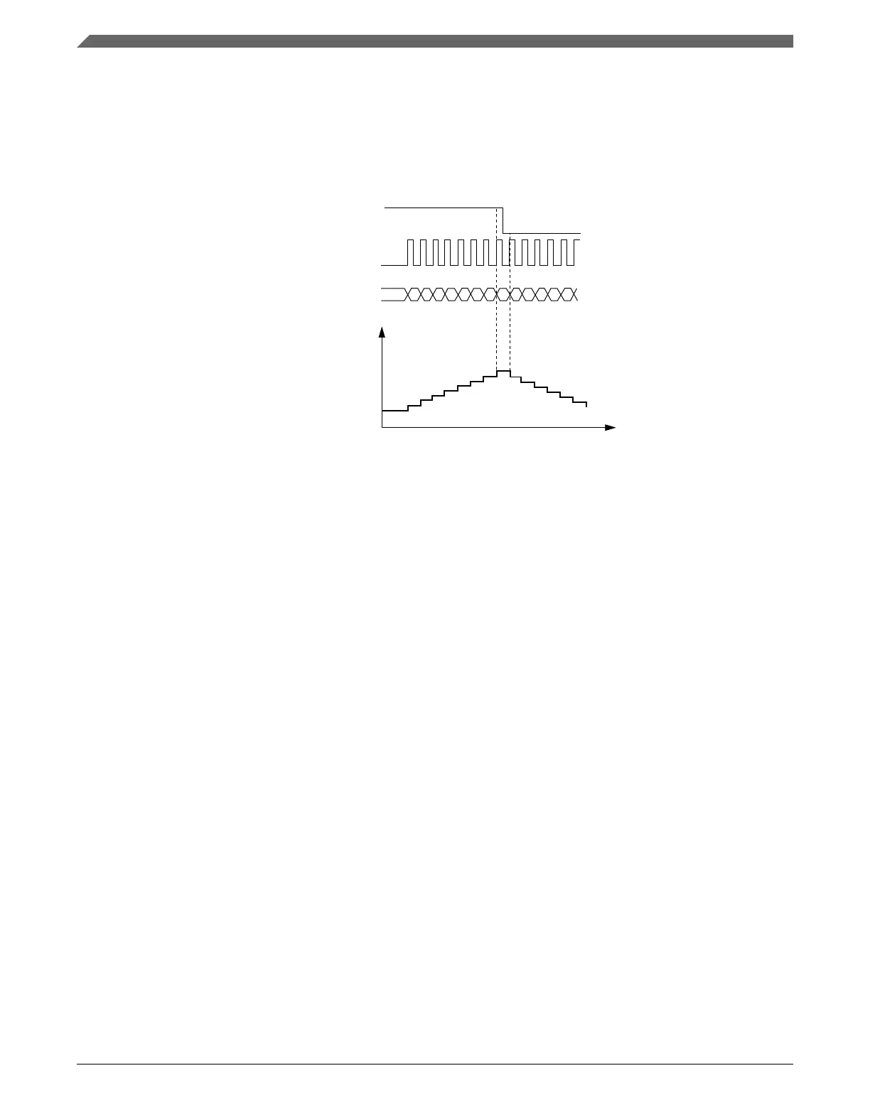
The QUADMODE selects the encoding mode used in the Quadrature Decoder mode. If
QUADMODE = 1, then the count and direction encoding mode is enabled; see the
following figure. In this mode, the phase B input value indicates the counting direction,
and the phase A input defines the counting rate. The FTM counter is updated when there
is a rising edge at phase A input signal.
phase B (counting direction)
phase A (counting rate)
FTM counter
increment/decrement
FTM counter
MOD
CNTIN
0x0000
Time
+1
+1
+1
+1
+1
+1
+1
+1
-1
-1
-1
-1
-1
Figure 39-90. Quadrature Decoder – Count and Direction Encoding mode
If QUADMODE = 0, then the Phase A and Phase B Encoding mode is enabled; see the
following figure. In this mode, the relationship between phase A and B signals indicates
the counting direction, and phase A and B signals define the counting rate. The FTM
counter is updated when there is an edge either at the phase A or phase B signals.
If PHAPOL = 0 and PHBPOL = 0, then the FTM counter increment happens when:
• there is a rising edge at phase A signal and phase B signal is at logic zero;
• there is a rising edge at phase B signal and phase A signal is at logic one;
• there is a falling edge at phase B signal and phase A signal is at logic zero;
• there is a falling edge at phase A signal and phase B signal is at logic one;
and the FTM counter decrement happens when:
• there is a falling edge at phase A signal and phase B signal is at logic zero;
• there is a falling edge at phase B signal and phase A signal is at logic one;
• there is a rising edge at phase B signal and phase A signal is at logic zero;
• there is a rising edge at phase A signal and phase B signal is at logic one.
Functional description
K22F Sub-Family Reference Manual, Rev. 4, 08/2016
1016 NXP Semiconductors

 Loading...