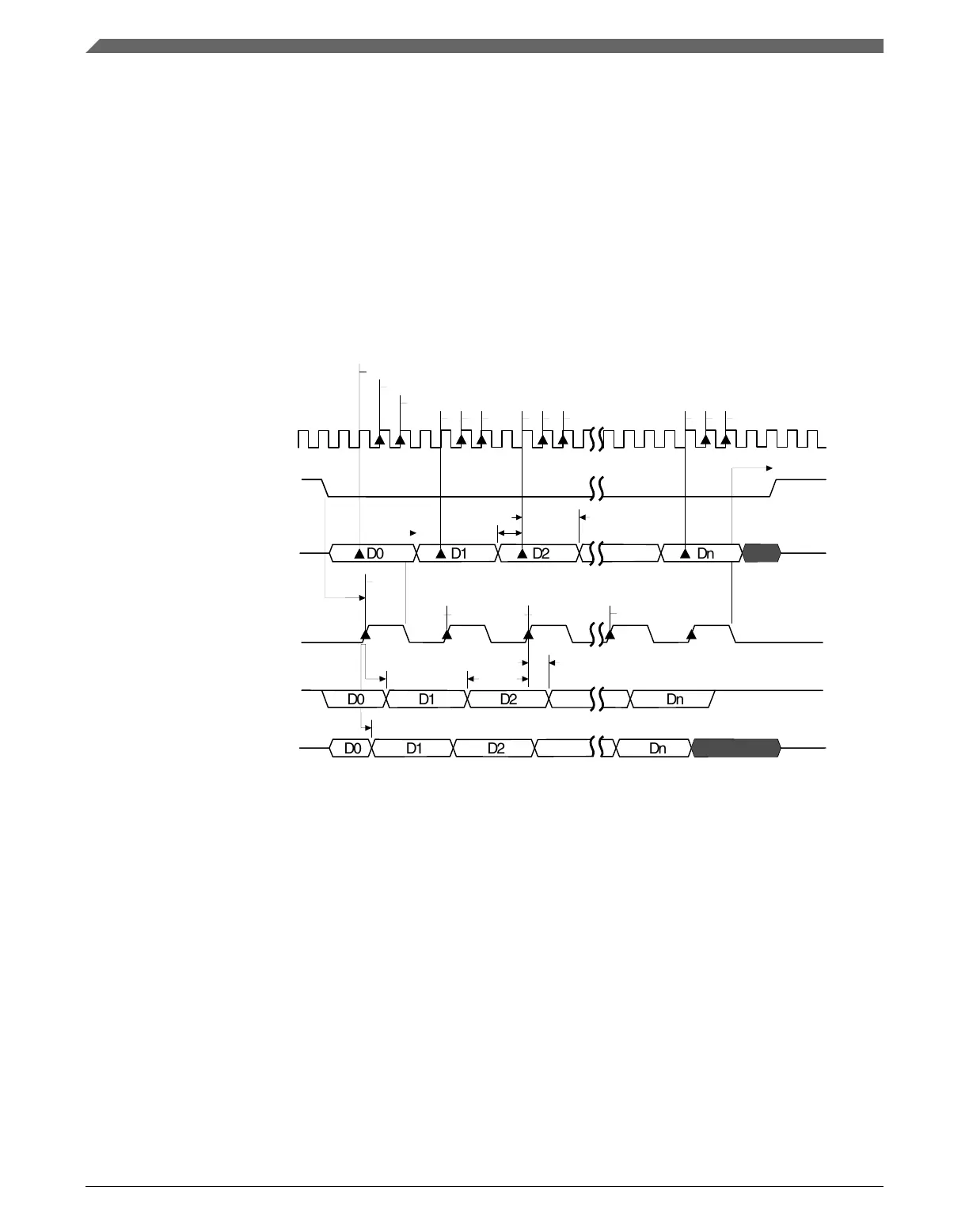
• Signal, marked "SOUT of Ext Slave", presents regular SPI slave serial output.
• Signal, marked "SOUT of DSPI Slave", presents DSPI in the slave mode with MTFE
bit set.
Other MTFE = 1 diagrams show DSPI SIN input as being driven by a regular external
SPI slave, configured according DSPI master CPHA programming.
Note
In the following diagrams, f
sys
represents the protocol clock
frequency from which the Baud frequency f
sck
is derived.
2n+2
DSPI samples SIN, SMPL_PT=0
D0 D1 D2 Dn
D0 D1 D2 Dn
D0 D1 D2 Dn
sys clk
PCS
SCK
SOUT
D1
D0
D2
Dn
Tcsc
Tvd_sl
Tsu_ms
Thd_ms
Tasc
Slave samples SOUT
Thd_sl
Tsu_sl
2n+1
6
5
4
3
2
1
Dn
D2
D1
D0
Dn
D2
D1
D0
Tvd_sl
Tsys
SMPL_PT=1
SMPL_PT=2
SOUT of DSPI Slave
SOUT of Ext Slave
Figure 45-8. DSPI Modified Transfer Format (MTFE=1, CPHA=0, f
sck
= f
sys
/4)
Functional description
K22F Sub-Family Reference Manual, Rev. 4, 08/2016
1164 NXP Semiconductors

 Loading...