Additionally, care must be taken to ensure that the reference clock divider (C1[FRDIV]
and C5[PRDIV0]) is set properly for the mode being switched to. For instance, in PEE
mode, if using a 4 MHz crystal, C5[PRDIV0] must be set to 5'b000 (divide-by-1) or
5'b001 (divide-by-2) to divide the external reference down to the required frequency
between 2 and 4 MHz
In FBE, FEE, FBI, and FEI modes, at any time, the application can switch the FLL
multiplication factor between 640, 1280, 1920, and 2560 with C4[DRST_DRS] bits.
Writes to C4[DRST_DRS] bits will be ignored if C2[LP]=1.
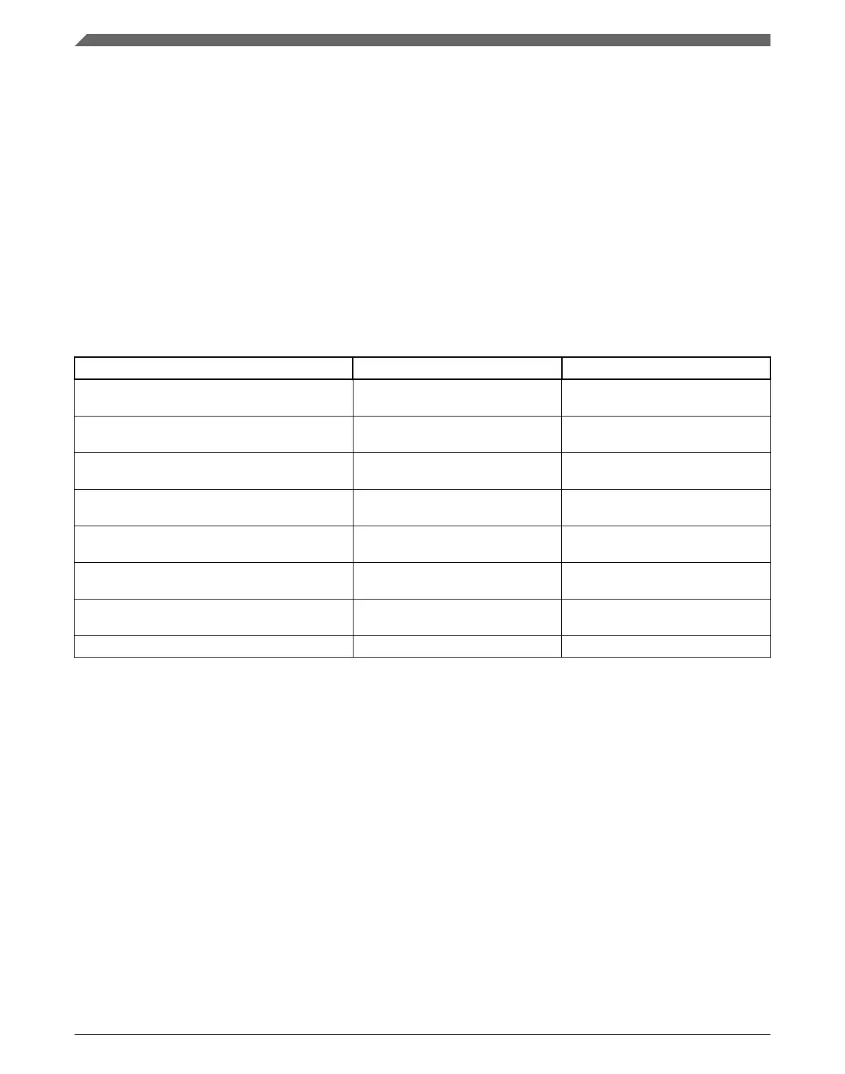
The table below shows MCGOUTCLK frequency calculations using C1[FRDIV],
C5[PRDIV0], and C6[VDIV0] settings for each clock mode.
Table 25-4. MCGOUTCLK Frequency Calculation Options
Clock Mode f
MCGOUTCLK
1
Note
FEI (FLL engaged internal) f
int
× F Typical f
MCGOUTCLK
= 21 MHz
immediately after reset.
FEE (FLL engaged external) (f
ext
/ FLL_R) × F f
ext
/ FLL_R must be in the range of
31.25 kHz to 39.0625 kHz
FBE (FLL bypassed external) OSCCLK OSCCLK / FLL_R must be in the
range of 31.25 kHz to 39.0625 kHz
FBI (FLL bypassed internal) MCGIRCLK Selectable between slow and fast
IRC
PEE (PLL engaged external) (OSCCLK / PLL_R) × M OSCCLK / PLL_R must be in the
range of 2 – 4 MHz
PBE (PLL bypassed external) OSCCLK OSCCLK / PLL_R must be in the
range of 2 – 4 MHz
BLPI (Bypassed low power internal) MCGIRCLK Selectable between slow and fast
IRC
BLPE (Bypassed low power external) OSCCLK
1. FLL_R is the reference divider selected by the C1[FRDIV] bits, F is the FLL factor selected by C4[DRST_DRS] and
C4[DMX32] bits , PLL_R is the reference divider selected by C5[PRDIV0] bits, and M is the multiplier selected by
C6[VDIV0] bits.
This section will include several mode switching examples, using an 4 MHz external
crystal. If using an external clock source less than 2 MHz, the MCG must not be
configured for any of the PLL modes (PEE and PBE).
Initialization / Application information
K22F Sub-Family Reference Manual, Rev. 4, 08/2016
568 NXP Semiconductors

 Loading...